RE65GR500C02 Vishay, RE65GR500C02 Datasheet - Page 4
RE65GR500C02
Manufacturer Part Number
RE65GR500C02
Description
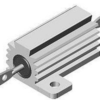
RH-10 .5 1% RE65GR500 C02
Manufacturer
Vishay
Type
Wirewoundr
Specifications of RE65GR500C02
Resistance
0.5 Ohms
Tolerance
1 %
Power Rating
10 Watts
Temperature Coefficient
+/- 100 PPM / C
Operating Temperature Range
- 55 C to + 250 C
Dimensions
10.67 mm Dia. x 20.32 mm W x 19.05 mm L x 9.91 mm H
Product
Power Resistors Wire Wound Aluminum Housed
Power Rating(s)
10W
Tolerance (+ Or -)
1%
Mounting Style
Flange
Construction
Chassis
Operating Temp Range
-55C to 250C
Case Style
Aluminum Housed
Termination Style
Axial
Military Standard
MIL-PRF-18546
Product Length (mm)
34.93mm
Product Height (mm)
9.91mm
Product Depth (mm)
20.32mm
Lead Free Status / Rohs Status
Lead free / RoHS Compliant


MATERIAL SPECIFICATIONS
Element: Copper-nickel alloy or nickel-chrome alloy,
depending on resistance value
Core: Ceramic, steatite or alumina, depending on physical
size
Encapsulant: Silicone molded construction
Housing: Aluminum with hard anodic coating
End Caps: Stainless steel
Standard Terminals: For RH100 and RH250 terminals are
threaded stainless steel. All others are 60/40 tin/lead (Sn/Pb)
w/Nickel underplate on copper clad steel core terminal.
Part Marking: Dale, model, wattage, value, tolerance, date
code
Document Number: 30282
Revision: 23-Feb-11
PERFORMANCE
TEST
Thermal Shock
Short Time Overload
Dielectric Withstanding Voltage
Temperature
Moisture Resistance
Shock, Specified Pulse
Vibration, High Frequency
Load Life
Terminal Strength
Wirewound Resistors, Military, MIL-PRF-18546 Qualified,
5 x rated power for 5 s
MIL-STD-202 Method 106, 7b not applicable
Rated power applied until thermally stable,
then a minimum of 15 min at - 55 °C
1000 V
4500 V
250 °C for 2 h
MIL-STD-202 Method 213, 100 g’s for 6 ms, 10 shocks
Frequency varied 10 Hz to 2000 Hz, 20 g peak, 2 directions 6 h each
1000 h at rated power, + 25 °C, 1.5 h “ON”, 0.5 h “OFF”
30 s, 5 pound pull test for RE60 and RE65,
10 pound pull test for other sizes;
torque test - 24 pound inch for RE77 and 32 pound inch for RE80
Type RE, Aluminum Housed, Chassis Mount
For technical questions, contact:
rms
rms
for RE60, RE65 and RE70; 2000 V
for RE77 and RE80; duration 1 min
CONDITIONS OF TEST
ww2bresistors@vishay.com
NON-INDUCTIVE (TYPE N)
Models of equivalent physical and electrical specifications
are available with non-inductive (Aryton-Perry) winding.
They are identified by substituting the letter N for G in the
model number (RE60N, for example).
rms
for RE75;
± (0.5 % + 0.05 ) R
± (0.5 % + 0.05 ) R
± (0.2 % + 0.05 ) R
± (0.5 % + 0.05 ) R
± (1.0 % + 0.05 ) R
± (0.2 % + 0.05 ) R
± (0.2 % + 0.05 ) R
± (1.0 % + 0.05 ) R
± (0.2 % + 0.05 ) R
RE Military
TEST LIMITS
Vishay Dale
www.vishay.com
4
Related parts for RE65GR500C02
Image
Part Number
Description
Manufacturer
Datasheet
Request
R

Part Number:
Description:
357-036-542-201 CARDEDGE 36POS DL .156 BLK LOPRO
Manufacturer:
Vishay
Datasheet:
Part Number:
Description:
357-036-542-201 CARDEDGE 36POS DL .156 BLK LOPRO
Manufacturer:
Vishay
Datasheet:
Part Number:
Description:
357-036-542-201 CARDEDGE 36POS DL .156 BLK LOPRO
Manufacturer:
Vishay
Datasheet:
Part Number:
Description:
357-036-542-201 CARDEDGE 36POS DL .156 BLK LOPRO
Manufacturer:
Vishay
Datasheet:
Part Number:
Description:
357-036-542-201 CARDEDGE 36POS DL .156 BLK LOPRO
Manufacturer:
Vishay
Datasheet:
Part Number:
Description:
357-036-542-201 CARDEDGE 36POS DL .156 BLK LOPRO
Manufacturer:
Vishay
Datasheet:
Part Number:
Description:
357-036-542-201 CARDEDGE 36POS DL .156 BLK LOPRO
Manufacturer:
Vishay
Datasheet:
Part Number:
Description:
357-036-542-201 CARDEDGE 36POS DL .156 BLK LOPRO
Manufacturer:
Vishay
Datasheet:
Part Number:
Description:
357-036-542-201 CARDEDGE 36POS DL .156 BLK LOPRO
Manufacturer:
Vishay
Datasheet:
Part Number:
Description:
357-036-542-201 CARDEDGE 36POS DL .156 BLK LOPRO
Manufacturer:
Vishay
Datasheet:
Part Number:
Description:
357-036-542-201 CARDEDGE 36POS DL .156 BLK LOPRO
Manufacturer:
Vishay
Datasheet:
Part Number:
Description:
357-036-542-201 CARDEDGE 36POS DL .156 BLK LOPRO
Manufacturer:
Vishay
Datasheet:
Part Number:
Description:
357-036-542-201 CARDEDGE 36POS DL .156 BLK LOPRO
Manufacturer:
Vishay
Datasheet:
Part Number:
Description:
357-036-542-201 CARDEDGE 36POS DL .156 BLK LOPRO
Manufacturer:
Vishay
Datasheet:
Part Number:
Description:
357-036-542-201 CARDEDGE 36POS DL .156 BLK LOPRO
Manufacturer:
Vishay
Datasheet: