352068-1 TE Connectivity, 352068-1 Datasheet - Page 70
352068-1
Manufacturer Part Number
352068-1
Description
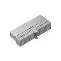
Conn Hard Metric RCP 110 POS 2mm Solder RA Thru-Hole
Manufacturer
TE Connectivity
Type
Hard Metricr
Series
Z-PACKr
Specifications of 352068-1
Pitch
2 mm
Number Of Rows
5
Number Of Contacts
110
Termination Method
Solder
Mounting
Through Hole
Contact Plating
Gold Over Nickel
Pitch (mm)
2mm
Gender
RCP
Body Orientation
Right Angle
Number Of Contact Rows
5
Mounting Style
Through Hole
Contact Resistance Max
20mOhm
Voltage Rating Max
500VAC
Current Rating (max)
1.5/ContactA
Operating Temp Range
-55C to 125C
Contact Material
Phosphor Bronze
Housing Color
Gray
Housing Material
Polyester
Product Height (mm)
12.25mm
Product Length (mm)
49.9mm
Connector Type
Hard Metric (HM)
Row Pitch
2mm
Pitch Spacing
2mm
No. Of Contacts
110
Contact Termination
Right Angle Press Fit
No. Of Rows
5
Rohs Compliant
Yes
Number Of Positions / Contacts
110
Termination Style
Solder Pin
Product Type
Connector
Pcb Mounting Orientation
Right Angle
Board Mount
Free Board
Module Length (mm [in])
50.00 [1.968]
Crosstalk Version
Standard
Shield Type
Ground Return Shielding
Shield Style
Upper
Shielded
Yes
Interface Type
2mm HM
Termination End Plating
Tin-Lead over Nickel
Number Of Positions
110
Grounding Contact
Without
Rows Loaded
A, B, E, D, C
Number Of Signal Contacts
110
Compactpci Designation
J1, J4
Contact Configuration
ACTION PIN Post, Signal
Feedthrough Post Length (mm [in])
3.70 [0.145]
Compactpci
Yes
Contact Plating, Mating Area, Material
Gold (30)
Contact Style
Short Tail
Contact Base Material
Phosphor Bronze
Connector Style
Receptacle
Mating Alignment
With
Mating Alignment Type
Multi-Purpose Center
Ul Flammability Rating
UL 94V-0
Rohs/elv Compliance
RoHS compliant, ELV compliant
Lead Free Solder Processes
Not relevant for lead free process
Rohs/elv Compliance History
Always was RoHS compliant
Lead Free Status / RoHS Status
Compliant
Lead Free Status / RoHS Status
Compliant


70
General Information
Layouts show Type M, L, N connectors,
for DIN contacts, in a typical stacking
arrangement, including signal contacts
on a 2 x 2 [.079 x .079] grid, with
optional ground return shielding.
Female Connector
Standard and Reduced Crosstalk
versions, see examples on page 63.
Symbols
Plated Through Holes:
Non-plated Through Holes:
* For reference only, please refer to
Power or Coax Contact customer
drawing for correct hole pattern.
Catalog 65911
Revised 7-05
www.tycoelectronics.com
Signal Contacts.
Row f odd numbers for upper
ground return shield.
Row f even numbers for lower
ground return shield.
Backplane rows z and f for
ground return shield contacts.
1.3
through holes for board mount
DIN high current or coaxial
contacts. To be omitted for cable
contacts.
Ø 2.0
polarizing, location peg hole
for press fit.
6.1
hole in fixed board, for DIN
high current and coaxial con-
tacts.*
Optional cutout, used for DIN
fiber optic contacts.*
+ 0.1 - 0
+ 0.05 -0
+ 0.1 - 0
[.051
[.079
[.240
+ .004
+ .002
+ .004
] plated
Dimensions are in millimeters
and inches unless otherwise
specified. Values in brackets
are standard equivalents.
]
]
AMP Z-PACK 2mm HM Hard Metric
Interconnection System
Page_Head
PC Board Layout for Type L, M, N Connectors
Type M
Type L
Type N
See page 9 for details of plated through holes.
[.051
Ø 1.3
Column
+ .004
+ 0.10
- 0.00
Row
2.5 [.098]
2.5 [.098]
]
[.098]
[.098]
2.5
2.5
15
16
17
18
19
20
21
22
23
24
25
Female Connectors
Component Side
Note:
(Continued)
f e d c b a
Right Angle
reference purposes only.
Dimensions are shown for
Specifications subject
to change.
Only required for coaxial/omitted for power.
2.0 [.079]
Ø 2.0
[.079
[.059]
[.079]
[.079]
3.5 [.138]
[.039]
1.5
2.0
2.0
1.0
+0.05
+.002
-0.00
6.25 [.246]
3.75 [.147]
3.75 [.148]
Board Edge
10 x 2.0
= 20.0
[.295]
[.295]
[.295]
[.295]
10.25
[.404]
[.787]
[.295]
[.295]
[.492]
[.295]
[.295]
[.295]
12.5
7.5
]
7.5
7.5
7.5
7.5
7.5
7.5
7.5
7.5
Note: For guidance only.
USA: 1-800-522-6752
Canada: 1-905-470-4425
Mexico: 01-800-733-8926
C. America: 52-55-5-729-0425
Consult customer
drawings for production
layouts
[1.968]
[1.968]
[.984]
50.0
50.0
25.0
10 x 2.0
= 20.0
[.787]
3.75 [.148]
3.75 [.148]
3.75 [.148]
3.75 [.148]
5.25 [.207]
[.246]
[.295]
5.5 [.217]
[.295]
[.295]
[.246]
[.295]
[.295]
[.246]
[.295]
[.295]
[.295]
[.157]
6.25
6.25
6.25
7.5
7.5
7.5
7.5
7.5
7.5
7.5
4.0
7.5
[.079
[.295
Ø 2.0
Row z
7.5
[.157
+ .002
r 4.0
+ 0.10
+ .004
+ 0.05
- 0.00
- 0.00
South America: 55-11-3611-1514
Hong Kong: 852-2735-1628
Japan: 81-44-844-8013
UK: 44-141-810-8967
Male Connector
a b c d e f
Front Side
]
+ 0.10
+ .004
- 0.00
]
Vertical
]
+
+
+
+
+
+
+
+
+
+
+
+
Ø 2.0
[.079
[.240
Ø 2.0
[.079
[.295
6.1
[.177]
7.5
+ 0.05
+ .002
4.5
- 0.00
15
16
17
18
19
20
21
22
23
24
25
+ 0.10
+ .004
+ 0.05
+ .002
+ 0.10
+ .004
- 0.00
- 0.00
- 0.00
]
]
]
]
Related parts for 352068-1
Image
Part Number
Description
Manufacturer
Datasheet
Request
R

Part Number:
Description:
Conn Hard Metric F 110 POS 2mm Press Fit RA Thru-Hole
Manufacturer:
TE Connectivity
Datasheet:

Part Number:
Description:
Hard Metric Connectors Z-PACK/A F-HDR 110P
Manufacturer:
TE Connectivity

Part Number:
Description:
Printers THERMAL PRINTER HS-SLEEVE MARKER
Manufacturer:
TE Connectivity


Part Number:
Description:
High Speed / Modular Connectors 30P HEADER ASSY
Manufacturer:
TE Connectivity
Datasheet:

Part Number:
Description:
High Speed / Modular Connectors REC 6X005P R/A LT B-PLANE HS3
Manufacturer:
TE Connectivity
Datasheet:

Part Number:
Description:
High Speed / Modular Connectors 2MM HM RCPT 50P R/A AU
Manufacturer:
TE Connectivity
Datasheet:

Part Number:
Description:
High Speed / Modular Connectors 2MM HM RCPT 50P R/A AU
Manufacturer:
TE Connectivity
Datasheet:


Part Number:
Description:
352=FUSE BLK SECTION T CLAMP
Manufacturer:
TE Connectivity
Datasheet:

Part Number:
Description:
Manufacturer:
TE Connectivity
Datasheet:


Part Number:
Description:
Manufacturer:
TE Connectivity
Datasheet:

Part Number:
Description:
Manufacturer:
TE Connectivity
Datasheet: