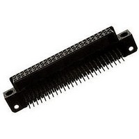
532431-1 TE Connectivity, 532431-1 Datasheet - Page 2

532431-1
Manufacturer Part Number
532431-1
Description
Conn HDI F 75 POS 2.54mm Solder RA Thru-Hole
Manufacturer
TE Connectivity
Type
HDIr
Series
AMP-HDIr
Specifications of 532431-1
Pitch
2.54 mm
Number Of Rows
3
Number Of Contacts
75
Termination Method
Solder
Mounting
Through Hole
Contact Plating
Gold Over Nickel
Pitch Spacing
2.54mm
No. Of Contacts
75
Gender
Receptacle
No. Of Rows
3
Contact Termination
Right Angle Through Hole
Contact Material
Copper Alloy
Rohs Compliant
No
Product Type
Connectors
Number Of Positions / Contacts
75
Mounting Style
Through Hole
Housing Material
Thermoplastic, Glass Filled
Pcb Mount Style
Through Hole
Pcb Mounting Orientation
Right Angle
Make First / Break Last
No
Pcb Mount Retention
Without
Termination Post Length (mm [in])
4.57 [0.180]
Solder Tail Contact Plating
Tin
Number Of Positions
75
Centerline (mm [in])
2.54 [0.100]
Contact Configuration
Four-Beam
Contact Plating, Mating Area, Material
Gold (30)
Contact Base Material
Copper Alloy
Underplate Material
Nickel
Mating Alignment
Without
Housing Color
Natural
Housing Material Temperature
High
Center Guide
Without
Government/industry Qualification
No
Rohs/elv Compliance
ELV compliant, 5 of 6 Compliant
Lead Free Solder Processes
Not suitable for lead free processing
Lead Free Status / Rohs Status
Details
Available stocks
Company
Part Number
Manufacturer
Quantity
Price
Company:
Part Number:
532431-1
Manufacturer:
SELMAC
Quantity:
8 150
3.4.
3.5.
Exam ination of product.
Term ination resistance, specified
current.
Term ination resistance, low level.
Dielectric withstanding voltage.
Insulation resistance.
Vibration.
Physical shock.
Mating force.
Rev C
Perform ance and Test Description
Connectors shall be designed to m eet electrical, m echanical and environm ental perform ance
requirem ents specified in Figure 1.
Test Requirem ents and Procedures Sum m ary
Test Description
.015 ohm s m axim um initial.
Meets requirem ents of product
drawing.
.015 ohm s m axim um initial.
.020 ohm s m axim um final.
.020 ohm s m axim um final.
2 m illiam peres m axim um leakage
current.
5000 m egohm s m inim um initial.
No discontinuities greater than 1
m icrosecond.
No physical dam age.
No discontinuities greater than 1
m icrosecond.
No physical dam age.
Term ination resistance, low level.
1.9 ounces m axim um average per
contact.
Test Voltage
(rm s)
900
200
Figure 1 (continued)
MECHANICAL
ELECTRICAL
Requirem ent
Sea Level
70,000
Altitude
Feet
Test between adjacent contacts of
Visual, dim ensional and functional
per applicable inspection plan.
Measure potential drop of m ated
contacts assem bled in housing
using 3 am peres m axim um
Calculate resistance.
See Figure 3.
TE Spec 109-25.
Subject m ated contacts assem bled
in housing to 50 m v open circuit at
100 m a m axim um .
See Figure 3.
TE Spec 109-6-1.
Tests between adjacent contacts of
unm ated connector and contacts to
hardware.
TE Spec 109-29-1.
unm ated connector and contacts to
hardware.
TE Spec 109-28-4.
Subject wired and m ated
connectors to 15 G's 10-2000 Hz
with 100 m a current applied.
TE Spec 109-21-3.
Subject wired and m ated connector
to 100 G's sawtooth shock pulses of
6 m illiseconds duration. 3 m utually
perpendicular planes, total 18
shocks.
TE Spec 109-26-9.
Measure force necessary to m ate
connector assem bly after 3
unm onitored cycles.
Calculate force per contact.
TE Spec 109-42, Condition A.
Procedure
108-9063
2 of 6


