5536504-2 TE Connectivity, 5536504-2 Datasheet
5536504-2
Specifications of 5536504-2


Related parts for 5536504-2


5536504-2 Summary of contents
Page 1
... Accessories and their identifying features are described and shown in Section 3 of this specification. When corresponding with TE Connectivity (TE) Personnel, use the terminology provided on this specification to help facilitate your inquiry for information. Basic terms and features of components are provided in Figure 1. ...
Page 2
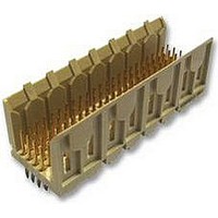
Alignment Rib Power Receptacle Contacts (Inside) Signal Receptacle Contacts (Inside) Power Pin Contact Alignment Rib Slot with Guide Solder Tine Contact Guide Post for Solder Type Only 5- - Row Vertical Power Standoff Pin Header Connector 2. REFERENCE ...
Page 3
Customer Assistance Reference Part Number 536507 and Product Code 1830 are representative numbers of Z--PACK 2mm FB Receptacle and Pin Header Connectors. Use of these numbers will identify the product line and expedite your inquiries through a service network ...
Page 4
Connector Features A. Materials All Z--PACK 2mm FB Connector Housings are constructed of high--temperature thermoplastic. The signal and power pin contacts are phosphor bronze and plated at the contact interface with gold flash over palladium--nickel. The signal receptacle contacts ...
Page 5
C. Guides The pin headers have alignment slots with a guide--in that helps position the pin and socket contacts prior to engagement of the circuits. See Figure 1. D. End- to- End Placement The end contacts in the pin header ...
Page 6
Mating Dimension Full mating of connectors is necessary to ensure a good connection. The dimension from the surface of the pc board to which the pin header is mounted and the first row of contacts in the receptacle must ...
Page 7
NOTE: Vertical connector pc board layouts are the same for both solder type and press fit except press fit does not have guide post holes. Right- - angle connector pc board layouts are the same for both solder type and ...
Page 8
NOTE: Vertical connector pc board layouts are the same for both solder type and press fit except press fit does not have guide post holes. Right- - angle connector pc board layouts are the same for both solder type and ...
Page 9
NUMBER OF SIGNAL POSITIONS 4- - ROW ------ 264 240 216 192 168 144 120 Contact Hole Configuration The contact holes in the pc board for all connectors must be prepared to the dimensions specified ...
Page 10
If using robotic equipment, a total equipment accuracy of +0.13 mm, including the gripper and fixture ...
Page 11
D. Soldering Guidelines Refer to Paragraph 2.4 for reference Manual 402--40 that is available for establishing soldering guidelines. 3.8. Inspection A. Solder Fillets All solder fillets should comply to the Workmanship Standard 101--21. For a typical fillet for these connectors, ...
Page 12
B. Right- Angle Connectors with Compliant Pins Place the connector in a housing support that has a slot wide enough and deep enough to receive the full length of the housing and contacts. Make sure the tool support will not ...
Page 13
TOOLING TE has existing tooling and tooling concepts for applying these connectors. Part numbers of available tools and the applicable instructional material for each is provided in Figure 12. Robotic Equipment S Robotic equipment for placement of connectors on ...
Page 14
Pin Repair Kit 354687 (For Removing and Replacing Damaged Contacts (408- - 9979) (4- - ROW) CONN CONN MODULE SEATING TOOL POSN TYPE (DOCUMENT) 24 58511--1 (408--9910) 48 58511--2 (408--9910) 72 1--58511--4 (408--9910) 96 58511--3 (408--9910) 120 58511--6 ...
Page 15
VISUAL AID Figure 13 shows a typical application of Z--PACK 2mm FB Connectors. This illustration should be used by production personnel to ensure a correctly applied product. Applications which DO NOT appear correct should be inspected using the information ...