145154-4 TE Connectivity, 145154-4 Datasheet - Page 57
145154-4
Manufacturer Part Number
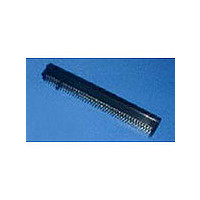
145154-4
Description
Conn PCI Express Card SKT 120 POS 1.27mm Solder ST Thru-Hole
Manufacturer
TE Connectivity
Type
PCI Express Cardr
Specifications of 145154-4
Number Of Contacts
120
Contact Plating
Gold Over Nickel
Mounting
Through Hole
Termination Method
Solder
Pitch
1.27 mm
Number Of Rows
2
Number Of Contact Rows
2
Body Orientation
Straight
Contact Material
Phosphor Bronze
Mounting Style
Through Hole
Product Height (mm)
15.49mm
Operating Temp Range
-55C to 85C
Pitch (mm)
1.27mm
Housing Material
Thermoplastic
Housing Color
White
Current Rating (max)
1/ContactA
Voltage Rating Max
203VAC
Contact Resistance Max
20
Connector Type
Card Edge
Row Pitch
2.54mm
Pitch Spacing
1.27mm
No. Of Contacts
120
Gender
Receptacle
Contact Termination
Through Hole Vertical
No. Of Rows
2
Rohs Compliant
No
Pcb Mounting Orientation
Vertical
Number Of Dual Positions
60
Pcb Mount Style
Through Hole
Termination Post Length (mm [in])
2.54 [0.100]
Solder Tail Contact Plating
Tin-Lead over Nickel
Number Of Positions
120
Centerline (mm [in])
1.27 [0.050]
Bus Width
32 Bit
Pcb Mount Retention Type
Pylon
Ejector
Without
Number Of Pylons
2
Pylon Material
Plastic
Family Name
PCI
Contact Plating, Mating Area, Material
Gold (30)
Contact Base Material
Phosphor Bronze
Rohs/elv Compliance
ELV compliant, 5 of 6 Compliant
Lead Free Solder Processes
Wave solder capable to 240°C, Wave solder capable to 260°C, Wave solder capable to 265°C
Lead Free Status / RoHS Status
Not Compliant


Catalog 1654080
Issued 7-03
www.tycoelectronics.com
Description/Application
Tyco Electronics can pro-
vide polarization keys in the
basic configuration shown
on this page. Our Modified
Bellows and Cantilever
Beam Series Card Edge
Connectors use these keys.
The part number and the
connector series for which it
was designed are listed in
the table below.
Per MIL-C-21097E
Dimensions are in inches and
millimeters unless otherwise
specified. Values in brackets
are metric equivalents.
Card Edge Connectors
(Solder Type, Board-to-Board)
Ordering Information
Card Edge Polarization Keys
Card Edge Connectors Recommended Daughter Card Edge Pattern
Daughter Card
* Except MIL-C-21097E 8–4 which is .070 [1.78]
NOTES:
1. Dimensions are in inches
2. Unless otherwise specified, tolerance is ±.005 [0.13 mm] for three place
3. Number of contact fingers shall be the same as the corresponding printed
Acquired Part
decimals.
wiring connector.
Slot Depth
Dim. A
98014-01
98014-01
Contact Spacing
Number
Min.
Non-Accum.
.100 [2.54]
.125 [3.18]
.156 [3.96]
.033
[.84]
Dimensions are shown for
reference purposes only.
Specifications subject
to change.
Break Off Point
Used on Connector
.105* [2.67]
±.005 (.13)
.093 [2.36]
.093 [2.36]
Modified Bellows
Cantilever Beam
Dim A
(Per Applicable Catalog Page)
Series
Dim. B
See Note 3
Contact Spacing
USA: 1-800-522-6752
Canada: 1-905-470-4425
Mexico: 01-800-733-8926
C. America: 52-55-5-729-0425
[4.83]
.19
.052 [1.32]
.052 [1.32]
.094 [2.39]
Dim B
Shown on
Pages
41-56
28-40
45°
[6.10]
.24
South America: 55-11-3611-1514
Hong Kong: 852-2735-1628
Japan: 81-44-844-8013
UK: 44-141-810-8967
Board Thickness
30°
.062 [1.57]
.015
[.38]
57
Related parts for 145154-4
Image
Part Number
Description
Manufacturer
Datasheet
Request
R

Part Number:
Description:
Conn Card Edge SKT 120 POS 1.27mm Solder ST Thru-Hole
Manufacturer:
TE Connectivity
Datasheet:

Part Number:
Description:
AMP .050C/L PCI 60 DUAL POS
Manufacturer:
TE Connectivity
Datasheet:

Part Number:
Description:
Printers THERMAL PRINTER HS-SLEEVE MARKER
Manufacturer:
TE Connectivity


Part Number:
Description:
High Speed / Modular Connectors 30P HEADER ASSY
Manufacturer:
TE Connectivity
Datasheet:

Part Number:
Description:
High Speed / Modular Connectors REC 6X005P R/A LT B-PLANE HS3
Manufacturer:
TE Connectivity
Datasheet:

Part Number:
Description:
High Speed / Modular Connectors 2MM HM RCPT 50P R/A AU
Manufacturer:
TE Connectivity
Datasheet:

Part Number:
Description:
High Speed / Modular Connectors 2MM HM RCPT 50P R/A AU
Manufacturer:
TE Connectivity
Datasheet:


Part Number:
Description:
Manufacturer:
TE Connectivity
Datasheet:


Part Number:
Description:
Manufacturer:
TE Connectivity
Datasheet:

Part Number:
Description:
Manufacturer:
TE Connectivity
Datasheet:
Part Number:
Description:
Manufacturer:
TE Connectivity
Datasheet: