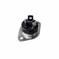
BTA25-600BW STMicroelectronics, BTA25-600BW Datasheet - Page 2

BTA25-600BW
Manufacturer Part Number
BTA25-600BW
Description
TRIAC 600V 25A RD-91
Manufacturer
STMicroelectronics
Series
Snubberless™r
Type
TRIACr
Datasheet
1.BTB24-600BWRG.pdf
(12 pages)
Specifications of BTA25-600BW
Triac Type
Alternistor - Snubberless
Mounting Type
Chassis Mount
Configuration
Single
Current - Hold (ih) (max)
75mA
Voltage - Off State
600V
Current - Gate Trigger (igt) (max)
50mA
Current - Non Rep. Surge 50, 60hz (itsm)
250A, 260A
Current - On State (it (rms)) (max)
25A
Voltage - Gate Trigger (vgt) (max)
1.3V
Package / Case
RD91-3 (Insulated)
Current - On State (it (rms) (max)
25A
Peak Repetitive Off-state Voltage, Vdrm
600V
Gate Trigger Current Max (qi), Igt
50mA
On State Rms Current It(rms)
25A
Peak Non Rep Surge Current Itsm 50hz
250A
Holding Current Max Ih
75mA
Repetitive Peak Off-state Volt
600V
Off-state Voltage
600V
Hold Current
75mA
Gate Trigger Current (max)
50mA
Gate Trigger Voltage (max)
1.3V
Package Type
RD-91
Peak Repeat Off Current
5uA
Peak Surge On-state Current (max)
260A
On State Voltage(max)
1.55@35AV
Mounting
Through Hole
Pin Count
3
Operating Temp Range
-40C to 125C
Operating Temperature Classification
Automotive
Rohs Compliant
Yes
Lead Free Status / RoHS Status
Lead free / RoHS Compliant
Other names
497-3125
497-3125-5
497-3125
497-3125-5
497-3125
Available stocks
Company
Part Number
Manufacturer
Quantity
Price
Company:
Part Number:
BTA25-600BW
Manufacturer:
ST
Quantity:
2 000
Characteristics
1
Table 2.
Table 3.
1. minimum I
2. for both polarities of A2 referenced to A1.
2/12
V
(dI/dt)c
Symbol
dV/dt
DSM
Symbol
I
P
I
T(RMS)
GT
V
I
V
I
dI/dt
T
I
H
TSM
G(AV)
I
GM
I
GD
T
GT
stg
(2)
L
²
/V
(1)
t
j
(2)
RSM
(2)
GT
V
V
T
I
I
V
Without snubber
Characteristics
Absolute maximum ratings
Electrical characteristics (T
logic level (3 quadrants) T25, BTA/BTB24...W, BTA25...W, BTA26...W
T
G
RMS on-state current (full sine wave)
Non repetitive surge peak on-state
current (full cycle, T
I
Critical rate of rise of on-state current
I
Non repetitive surge peak off-state
voltage
Peak gate current
Average gate power dissipation
Storage junction temperature range
Operating junction temperature range
²
G
j
D
D
D
is guaranted at 5% of I
t Value for fusing
= 500 mA
= 125° C
= 1.2 I
= 2 x I
= 12 V R
= V
= 67 %V
DRM
GT
GT
Test Conditions
DRM
, t
R
L
L
r
= 33 Ω
≤ 100 ns
= 3.3 kΩ
gate open
j
GT
initial = 25° C)
max.
Parameter
j
= 25° C, unless otherwise specified), Snubberless and
TOP3
D
TO-220AB
RD91 Ins/
TOP3 Ins.
TO-220AB Ins.
F = 50 Hz
F = 60 Hz
t
F = 120 Hz
t
t
p
p
p
2
= 10 ms
= 10 ms
= 20 µs
PAK /
T
T
Quadrant
j
j
I - II - III
I - II - III
I - II - III
= 125° C
= 125° C
I - III
II
BTA24, BTB24, BTA25, BTA26, BTB26, T25
MAX.
MAX.
MAX.
MAX.
MIN.
MIN.
MIN.
T
T
T
T
t = 20 ms
t = 16.7 ms
T
T
T
T
c
c
c
c
j
j
j
j
= 125° C
= 25° C
= 125° C
= 125° C
= 105° C
= 100° C
= 100° C
= 75° C
T2535
T25
500
35
50
70
80
13
- 40 to + 150
- 40 to + 125
CW
500
1.3
0.2
V
35
50
70
80
13
BTA/BTB
DRM
Value
+ 100
250
260
340
25
50
4
1
/V
RRM
1000
BW
100
50
75
80
22
Unit
A/µs
A/ms
A
V/µs
° C
Unit
mA
mA
mA
W
A
A
V
A
V
V
²
s


