Output ................................................................................2-bit quadrature code, Channel A leads Channel B electrically turning clockwise (CW)
Closed Circuit Resistance .............................................................................................................................................................. 5 ohms maximum
Contact Rating ......................................................................................................................................................................... TTL compatible loads
Insulation Resistance (500 VDC) ....................................................................................................................................... 1,000 megohms minimum
Dielectric Withstanding Voltage
Electrical Travel .........................................................................................................................................................................................Continuous
Contact Bounce .................................................................................................................................................................. 5 milliseconds maximum
RPM (Operating) ................................................................................................................................................................................... 120 maximum
Operating Temperature Range .........................................................................................................................-40 °C to +125 °C (-40 °F to +257 °F)
Storage Temperature Range ............................................................................................................................-55 ºC to +125 ºC (-67 °F to +257 °F)
Humidity ................................................................................................................................................... MIL-STD-202, Method 103B, Condition B
Vibration ...............................................................................................................................................................................................................30 G
Shock .................................................................................................................................................................................................................100 G
Rotational Life ......................................................................................................................................................................100,000 cycles @ 6 PPR
IP Rating .............................................................................................................................................................................................................. IP 67
Mechanical Angle ............................................................................................................................................................................ 360 ° Continuous
Running Torque ........................................................................................................................................................ 3.53 N-cm (5 oz.-in.) maximum
Mounting Torque
Weight .............................................................................................................................................................................................. 4.5 gm (0.15 oz.)
Terminals ............................................................................................................................................................................................ Solderable pins
Marking ...............................................................................................................................Manufacturer’s trademark, part number, and date code
Hardware .................................. One lockwasher and one mounting nut are shipped with each encoder, except where noted in the part number.
*RoHS Directive 2002/95/EC Jan 27, 2003 including Annex.
Specifi cations are subject to change without notice.
Customers should verify actual device performance in their specifi c applications.
Electrical Characteristics
Environmental Characteristics
Mechanical Characteristics
Suggested Incremental Control Diagram
Sea Level .................................................................................................................................................................................. 900 VAC minimum
Contact Bounce ............................................................................................................................................................ 5.0 millisecond maximum
Contact Bounce ............................................................................................................................................................ 5.0 millisecond maximum
Plastic Bushing................................................................................................................................................. 45.19 N-cm (4.0 lb.-in.) maximum
Metal Bushing ....................................................................................................................................................... 79 N-cm (7.0 lb.-in.) maximum
Soldering Condition
Manual Soldering .................................... 96.5Sn/3.0Ag/0.5Cu solid wire or no-clean rosin cored wire; 370 °C (700 °F) max. for 3 seconds
Wave Soldering ............................................................. 96.5Sn/3.0Ag/0.5Cu solder with no-clean fl ux; 260 °C (500 °F) max. for 5 seconds
Wash Processes ........................................... For recommended wash processes, please refer to http://www.bourns.com/pdfs/sldclen.pdf
7
5 ms DELAY
(MC 14490)
DEBOUNCE
.0015 f
9
Features
■
■
■
■
■
■
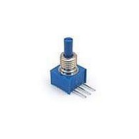
3315 - 9 mm Square Sealed Incremental Encoder
Miniature package for design fl exibility
Long operating life
Conductive plastic element
Bushing or PC board mount
Quadrature output
RoHS compliant versions available*
DECODE
LOGIC
(CUSTOMER LOGIC CIRCUITRY)
MAGNITUDE
DIRECTION
UP/DOWN
COUNTER
OUTPUT
BINARY
Quadrature Output Table
Channel A
Channel B
Channel C
Clockwise
25,000 cycles @ 16 PPR