HEDS-5540#F14 Avago Technologies US Inc., HEDS-5540#F14 Datasheet - Page 3
HEDS-5540#F14
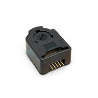
Manufacturer Part Number
HEDS-5540#F14
Description
Encoders 3 Channel 256 CPR 5mm Metal CW
Manufacturer
Avago Technologies US Inc.
Datasheet
1.HEDS-5540F14.pdf
(12 pages)
Specifications of HEDS-5540#F14
Number Of Channels
3
Mounting Style
Screw
Output
Quadrature with Index
Supply Voltage
5 V
Operating Temperature Range
- 40 C to + 100 C
Product
Kits
Pulses Per Revolution
256 CPR
Termination Style
Solder Pin
Lead Free Status / RoHS Status
Lead free / RoHS Compliant
Available stocks
Company
Part Number
Manufacturer
Quantity
Price


Theory of Operation
The HEDS-5500, 5540, 5600, 5640, and HEDM-5500, 5540,
5600 translate the rotary motion of a shaft into either a
two- or a three-channel digital output.
As seen in the block diagram, these encoders contain a
single Light Emitting Diode (LED) as its light source. The
light is collimated into a parallel beam by means of a
single polycarbonate lens located directly over the LED.
Opposite the emitter is the integrated detector circuit.
This IC consists of multiple sets of photodetectors and
the signal processing circuitry necessary to produce the
digital waveforms.
The codewheel rotates between the emitter and detector,
causing the light beam to be interrupted by the pattern
of spaces and bars on the codewheel. The photodi-
odes which detect these interruptions are arranged in a
pattern that corresponds to the radius and design of the
codewheel. These detectors are also spaced such that a
light period on one pair of detectors corresponds to a
dark period on the adjacent pair of detectors. The photo-
diode outputs are then fed through the signal processing
circuitry resulting in A, A, B and B (also I and I in the HEDS-
5540/5640 and HEDM-5540). Comparators receive these
signals and produce the final outputs for channels A and
B. Due to this integrated phasing technique, the digital
output of channel A is in quadrature with that of channel
B (90 degrees out of phase).
In the HEDS-5540/5640 and HEDM-5540, the output of
the comparator for I and I is sent to the index processing
circuitry along with the outputs of channels A and B.
The final output of channel I is an index pulse PO which
is generated once for each full rotation of the codewheel.
This output PO is a one state width (nominally 90 electri-
cal degrees), high true index pulse which is coincident
with the low states of channels A and B.
Block Diagram
Note: Circuitry for CH I is only for HEDS-5540, 5640 and HEDM 5540 Three Channel Encoder
3
Definitions
Count (N): The number of bar and window pairs or counts
per revolution (CPR) of the codewheel.
One Cycle (C): 360 electrical degrees (°e), 1 bar and window
pair.
One Shaft Rotation: 360 mechanical degrees, N cycles.
Position Error (∆Θ): The normalized angular difference
between the actual shaft position and the position
indicated by the encoder cycle count.
Cycle Error (∆C): An indication of cycle uniformity. The
differ¬ence between an observed shaft angle which
gives rise to one electrical cycle, and the nominal angular
increment of 1/N of a revolution.
Pulse Width (P): The number of electrical degrees that an
output is high during 1 cycle. This value is nominally 180°e
or 1/2 cycle.
Pulse Width Error ( ∆P): The deviation, in electrical degrees, of
the pulse width from its ideal value of 180°e.
State Width (S): The number of electrical degrees between a
transition in the output of channel A and the neighbour-
ing transition in the output of channel B. There are 4 states
per cycle, each nominally 90°e.
State Width Error ( ∆S): The deviation, in electrical degrees, of
each state width from its ideal value of 90°e.
Phase (φ): The number of electrical degrees between the
center of the high state of channel A and the center of the
high state of channel B. This value is nominally 90°e for
quadrature output.
Phase Error (∆φ): The deviation of the phase from its ideal
value of 90°e.
Related parts for HEDS-5540#F14
Image
Part Number
Description
Manufacturer
Datasheet
Request
R

Part Number:
Description:
ENCODER OPTICAL GAP 3CH 500CPR
Manufacturer:
Avago Technologies US Inc.
Datasheet:

Part Number:
Description:
Encoders 2 Channel 256CPR
Manufacturer:
Avago Technologies US Inc.
Datasheet:
Part Number:
Description:
Encoders 2 Channel 150CPR
Manufacturer:
Avago Technologies US Inc.
Datasheet:
Part Number:
Description:
Encoders 2 Channel 120CPR
Manufacturer:
Avago Technologies US Inc.
Datasheet:
Part Number:
Description:
SML ENC MOD 2CH BENT LDS 100 CPR
Manufacturer:
Avago Technologies US Inc.
Datasheet:
Part Number:
Description:
Encoders 2 Channel 400CPR
Manufacturer:
Avago Technologies US Inc.
Datasheet:

Part Number:
Description:
Encoders 2 Channel 180CPR
Manufacturer:
Avago Technologies US Inc.
Datasheet:
Part Number:
Description:
Encoders 2 Channel 400CPR
Manufacturer:
Avago Technologies US Inc.
Datasheet:
Part Number:
Description:
Encoders 2 Channel 150CPR
Manufacturer:
Avago Technologies US Inc.
Datasheet:
Part Number:
Description:
Encoders 2 Channel 150CPR
Manufacturer:
Avago Technologies US Inc.
Datasheet:
Part Number:
Description:
Encoders 2 Channel 150CPR
Manufacturer:
Avago Technologies US Inc.
Datasheet:
Part Number:
Description:
Encoders 2 Channel 150CPR
Manufacturer:
Avago Technologies US Inc.
Datasheet:
Part Number:
Description:
Encoders 2 Channel 360CPR
Manufacturer:
Avago Technologies US Inc.
Datasheet:
Part Number:
Description:
Encoders 2 Channel 150CPR
Manufacturer:
Avago Technologies US Inc.
Datasheet:
Part Number:
Description:
Encoders 2 Channel 400CPR
Manufacturer:
Avago Technologies US Inc.
Datasheet: