BT131-600D,412 NXP Semiconductors, BT131-600D,412 Datasheet
BT131-600D,412
Specifications of BT131-600D,412
934058136412
BT131-600D


Related parts for BT131-600D,412


BT131-600D,412 Summary of contents
Page 1
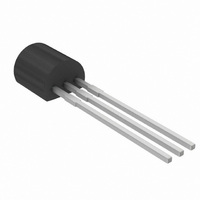
... BT131 series D and E Triacs logic level Rev. 02 — 17 November 2005 1. Product profile 1.1 General description Passivated, sensitive gate triacs in a SOT54 plastic package. 1.2 Features Designed to be interfaced directly to microcontrollers, logic integrated circuits and other low power gate trigger circuits. ...
Page 2
... Although not recommended, off-state voltages up to 800 V may be applied without damage, but the triac may switch to the on-state. The rate of rise of current should not exceed BT131_SER_D_E_2 Product data sheet BT131 series D and E Conditions all conduction angles 51.2 C; see Figure 1, ...
Page 3
... Fig 1. Total power dissipation as a function of RMS on-state current; maximum values 16 I TSM ( Fig 2. Non-repetitive peak on-state current as a function of the number of sinusoidal current cycles; maximum values BT131_SER_D_E_2 Product data sheet BT131 series D and E 0.4 0.6 10 Rev. 02 — 17 November 2005 Triacs logic level 003aab038 =180 120 0 ...
Page 4
... Fig 4. RMS on-state current as a function of surge duration, for sinusoidal currents; maximum values BT131_SER_D_E_2 Product data sheet ( 003aab042 I T(RMS surge duration (s) (1) T Fig 5. RMS on-state current as a function of lead Rev. 02 — 17 November 2005 BT131 series D and max (s) p 1.2 51.2 C (A) 0.8 0 ...
Page 5
... Mounted on a printed-circuit board; lead length = th(j-lead) (K/ (1) half cycle (2) full cycle Fig 6. Transient thermal impedance as a function of pulse duration BT131_SER_D_E_2 Product data sheet BT131 series D and E Conditions full cycle half cycle see Figure 6 (1) ( Rev. 02 — 17 November 2005 Triacs logic level Min Typ Max - - 60 - ...
Page 6
... Figure 100 mA; see Figure 400 125 125 C D DRM(max 400 125 /dt = 0.5 A/ms com DRM(max 125 C; exponential j waveform see Figure 1 DRM(max 100 mA Rev. 02 — 17 November 2005 BT131 series D and E BT131-600D BT131-600E BT131-800D BT131-800E Min Typ Max Min Typ - - 1 1.3 - 1.2 1 ...
Page 7
... 125 C; typical values j ( 125 C; maximum values j ( maximum values j Fig 9. On-state current characteristics BT131_SER_D_E_2 Product data sheet BT131 series D and E 003aab043 3 I GT(Tj) I GT(25 C) (1) 2 (2) (3) ( 100 150 ( ( (3) T2+ G (4) T2+ G+ Fig 8. Normalized gate trigger current as a function of ...
Page 8
... Philips Semiconductors 3 I H(Tj Fig 11. Normalized holding current as a function of junction temperature 7. Package information Epoxy meets requirements of UL94 V-0 at BT131_SER_D_E_2 Product data sheet BT131 series D and E 001aab099 / 100 150 (1) BT131-600E, BT131-800E (2) BT131-600D, BT131-800D Fig 12. Rate of rise of off-state voltage as a function of junction temperature ...
Page 9
... L 4.8 1.7 4.2 14.5 2.54 1.27 4.4 1.4 3.6 12.7 REFERENCES JEDEC JEITA TO-92 SC-43A Rev. 02 — 17 November 2005 BT131 series D and E Triacs logic level ( max. 2.5 EUROPEAN PROJECTION © Koninklijke Philips Electronics N.V. 2005. All rights reserved. SOT54 ISSUE DATE ...
Page 10
... BT131_SER_D_E_1 20040501 BT131_SER_D_E_2 Product data sheet Data sheet status Change notice Product data sheet - 5: corrected. Product - specification Rev. 02 — 17 November 2005 BT131 series D and E Triacs logic level Doc. number Supersedes - BT131_SER_D_E_1 - - © Koninklijke Philips Electronics N.V. 2005. All rights reserved ...
Page 11
... Trademarks Notice — All referenced brands, product names, service names and trademarks are the property of their respective owners. Rev. 02 — 17 November 2005 BT131 series D and E Triacs logic level © Koninklijke Philips Electronics N.V. 2005. All rights reserved ...
Page 12
... Trademarks Contact information . . . . . . . . . . . . . . . . . . . . 11 BT131 series D and E © Koninklijke Philips Electronics N.V. 2005 All rights are reserved. Reproduction in whole or in part is prohibited without the prior written consent of the copyright owner. The information presented in this document does not form part of any quotation or contract, is believed to be accurate and reliable and may be changed without notice ...