IR2 1K 10% Vishay, IR2 1K 10% Datasheet - Page 2
IR2 1K 10%
Manufacturer Part Number
IR2 1K 10%
Description
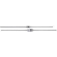
Common Mode Inductors (Chokes) 1KuH 10%
Manufacturer
Vishay
Datasheet
1.IR02BH8R2K.pdf
(4 pages)
Specifications of IR2 1K 10%
Inductance
1 uH
Tolerance
10 %
Maximum Dc Current
385 mAmps
Maximum Dc Resistance
1 Ohms
Self Resonant Frequency
230 MHz
Q Minimum
25
Operating Temperature Range
- 55 C to + 125 C
Termination Style
Axial
Dimensions
3.050 mm W x 8.380 mm L
Shielding
Shielded
Test Frequency
25 MHz
Lead Free Status / RoHS Status
Lead free / RoHS Compliant


IR
Vishay Dale
Notes
(1)
(2)
www.vishay.com
2
STANDARD ELECTRICAL SPECIFICATIONS
MODEL
IR-2
IR-2
IR-2
IR-2
IR-2
IR-2
IR-2
IR-2
IR-2
IR-2
IR-2
IR-2
IR-2
IR-2
IR-2
IR-2
IR-2
IR-2
IR-2
IR-2
IR-2
IR-2
IR-2
IR-2
IR-2
IR-2
IR-2
IR-2
IR-2
IR-2
IR-2
IR-2
IR-2
IR-2
IR-2
IR-2
IR-2
IR-2
IR-2
IR-2
IR-2
IR-2
IR-2
IR-2
IR-2
IR-2
IR-2
IR-2
IR-2
IR-4
IR-4
IR-4
IR-4
IR-4
IR-4
IR-4
IR-4
IR-4
IR-4
IR-4
IR-4
IR-4
IR-4
IR-4
IR-4
Measured with full length lead
Rated DC Current based on maximum temperature rise as shown in table
1000.0
100.0
120.0
150.0
180.0
220.0
270.0
330.0
390.0
470.0
560.0
680.0
820.0
IND.
0.10
0.12
0.15
0.18
0.22
0.27
0.33
0.39
0.47
0.56
0.68
0.82
10.0
12.0
15.0
18.0
22.0
27.0
33.0
39.0
47.0
56.0
68.0
82.0
0.15
0.22
0.33
0.47
0.56
0.68
0.82
(μH)
1.0
1.2
1.5
1.8
2.2
2.7
3.3
3.9
4.7
5.6
6.8
8.2
1.0
1.2
1.5
1.8
2.2
2.7
3.3
3.9
4.7
TOL.
± 10
± 10
± 10
± 10
± 10
± 10
± 10
± 10
± 10
± 10
± 10
± 10
± 10
± 10
± 10
± 10
± 10
± 10
± 10
± 10
± 10
± 10
± 10
± 10
± 10
± 10
± 10
± 10
± 10
± 10
± 10
± 10
± 10
± 10
± 10
± 10
± 10
± 10
± 10
± 10
± 10
± 10
± 10
± 10
± 10
± 10
± 10
± 10
± 10
± 20
± 20
± 20
± 20
± 10
± 10
± 10
± 10
± 10
± 10
± 10
± 10
± 10
± 10
± 10
± 10
(%)
MIN.
40
40
38
35
33
33
30
30
30
30
28
28
25
25
28
30
30
37
45
45
45
50
50
55
55
45
40
50
50
50
45
45
45
45
50
50
50
30
30
30
30
30
30
30
30
30
30
30
30
50
50
45
45
50
50
50
50
33
33
33
33
33
33
33
33
Q
For technical questions, contact:
Inductors, Epoxy Conformal Coated,
Uniform Roll Coated, Axial Leaded
TEST FREQUENCY L AND Q
(MHz)
25.0
25.0
25.0
25.0
25.0
25.0
25.0
25.0
25.0
25.0
25.0
25.0
25.0
0.79
0.79
0.79
0.79
0.79
0.79
0.79
0.79
0.79
0.79
0.79
0.79
25.0
25.0
25.0
25.0
25.0
25.0
25.0
25.0
7.9
7.9
7.9
7.9
7.9
7.9
7.9
7.9
7.9
7.9
7.9
7.9
2.5
2.5
2.5
2.5
2.5
2.5
2.5
2.5
2.5
2.5
2.5
2.5
7.9
7.9
7.9
7.9
7.9
7.9
7.9
7.9
magnetics@vishay.com
SRF MIN.
(MHz)
680.0
640.0
600.0
550.0
510.0
430.0
410.0
365.0
330.0
300.0
275.0
250.0
230.0
150.0
140.0
125.0
115.0
100.0
525.0
450.0
360.0
310.0
280.0
250.0
220.0
200.0
180.0
160.0
150.0
135.0
120.0
110.0
100.0
90.0
80.0
75.0
65.0
60.0
55.0
50.0
40.0
35.0
30.0
25.0
20.0
24.0
22.0
20.0
18.0
15.0
14.0
13.0
12.0
11.0
10.0
90.0
9.0
8.0
7.0
6.5
6.0
5.0
4.0
3.8
3.4
(1)
DCR MAX.
0.055
0.135
0.08
0.09
0.10
0.12
0.14
0.16
0.22
0.30
0.35
0.50
0.60
0.85
1.00
0.18
0.22
0.30
0.40
0.55
0.85
13.0
15.0
17.0
21.0
25.0
28.0
35.0
42.0
46.0
60.0
65.0
72.0
0.03
0.09
0.12
0.15
0.22
0.29
0.42
0.50
0.65
0.95
1.20
2.00
2.30
2.60
(Ω)
1.0
1.2
1.8
2.0
2.7
3.7
2.7
2.8
3.1
3.3
3.5
3.4
3.6
4.5
5.7
6.7
7.3
8.0
Document Number: 34054
RATED DC CURRENT
Revision: 15-Jul-09
1350
1270
1200
1105
1025
2450
1810
1400
1225
1150
1100
960
815
700
650
545
495
415
385
590
535
455
395
355
270
250
230
185
175
155
130
155
150
145
140
135
130
125
110
100
900
785
650
600
525
435
385
300
280
260
(mA)
92
88
84
66
61
57
52
47
45
40
36
35
30
29
28
(2)
Related parts for IR2 1K 10%
Image
Part Number
Description
Manufacturer
Datasheet
Request
R

Part Number:
Description:
Common Mode Inductors (Chokes) .56uH 10%
Manufacturer:
Vishay
Datasheet:
Part Number:
Description:
Common Mode Inductors (Chokes) 4.7uH 10%
Manufacturer:
Vishay
Datasheet:
Part Number:
Description:
Common Mode Inductors (Chokes) 5.6uH 10%
Manufacturer:
Vishay
Datasheet:
Part Number:
Description:
Common Mode Inductors (Chokes) 180uH 10%
Manufacturer:
Vishay
Datasheet:
Part Number:
Description:
Common Mode Inductors (Chokes) 5.6uH 5%
Manufacturer:
Vishay
Datasheet:
Part Number:
Description:
Common Mode Inductors (Chokes) .22uH 10%
Manufacturer:
Vishay
Datasheet:
Part Number:
Description:
Common Mode Inductors (Chokes) 2.2uH 10%
Manufacturer:
Vishay
Datasheet:

Part Number:
Description:
357-036-542-201 CARDEDGE 36POS DL .156 BLK LOPRO
Manufacturer:
Vishay
Datasheet:
Part Number:
Description:
357-036-542-201 CARDEDGE 36POS DL .156 BLK LOPRO
Manufacturer:
Vishay
Datasheet:
Part Number:
Description:
357-036-542-201 CARDEDGE 36POS DL .156 BLK LOPRO
Manufacturer:
Vishay
Datasheet:
Part Number:
Description:
357-036-542-201 CARDEDGE 36POS DL .156 BLK LOPRO
Manufacturer:
Vishay
Datasheet:
Part Number:
Description:
357-036-542-201 CARDEDGE 36POS DL .156 BLK LOPRO
Manufacturer:
Vishay
Datasheet:
Part Number:
Description:
357-036-542-201 CARDEDGE 36POS DL .156 BLK LOPRO
Manufacturer:
Vishay
Datasheet:
Part Number:
Description:
357-036-542-201 CARDEDGE 36POS DL .156 BLK LOPRO
Manufacturer:
Vishay
Datasheet:
Part Number:
Description:
357-036-542-201 CARDEDGE 36POS DL .156 BLK LOPRO
Manufacturer:
Vishay
Datasheet: