IRF46RU123K Vishay, IRF46RU123K Datasheet

Common Mode Inductors (Chokes) IRF-46 12000uH 10%

IRF46RU123K

Manufacturer Part Number
IRF46RU123K
Description
Common Mode Inductors (Chokes) IRF-46 12000uH 10%
Manufacturer
Vishay
Series
IRF-46r
Datasheet

Specifications of IRF46RU123K

Inductance
12 mH
Tolerance
10 %
Maximum Dc Current
60 mAmps
Maximum Dc Resistance
0.4 Ohms
Self Resonant Frequency
88 MHz
Q Minimum
50
Operating Temperature Range
- 20 C to + 105 C
Termination Style
Axial
Product
Inductors
Dimensions
5 mm Dia. x 6 mm L
Shielding
Unshielded
Test Frequency
2.5 MHz
Lead Free Status / RoHS Status
Lead free / RoHS Compliant
ELECTRICAL SPECIFICATIONS
Inductance Range: 1000 μH to 39 000 μH
Inductance Tolerance: ± 10 % standard, ± 5 % optional
Operating Temperature Range: - 20 °C to + 105 °C
Dielectric Strength: 250 V
MECHANICAL SPECIFICATIONS
Terminal Strength: Pull = 5 pounds, twist = 360 °C x 3
Protection: Epoxy uniform roll coated
Leads: Tinned copper
ENVIRONMENTAL SPECIFICATIONS
Maximum Temperature Rise: + 20 °C
Document Number: 34058
Revision: 24-Feb-11
STANDARD ELECTRICAL SPECIFICATIONS
MODEL
IRF-46
IRF-46
IRF-46
IRF-46
IRF-46
IRF-46
IRF-46
IRF-46
IRF-46
IRF-46
IRF-46
IRF-46
IRF-46
IRF-46
IRF-46
IRF-46
IRF-46
IRF-46
IRF-46
IRF-46
IRF-46
10 000
12 000
15 000
18 000
22 000
27 000
30 000
33 000
39 000
1000
1200
1500
1800
2200
2700
3300
3900
4700
5600
6800
8200
IND.
(μH)
Inductors, Epoxy Conformal Coated, Axial Leaded
± 5, ± 10
± 5, ± 10
± 5, ± 10
± 5, ± 10
± 5, ± 10
± 5, ± 10
± 5, ± 10
± 5, ± 10
± 5, ± 10
± 5, ± 10
± 5, ± 10
± 5, ± 10
± 5, ± 10
± 5, ± 10
± 5, ± 10
± 5, ± 10
± 5, ± 10
± 5, ± 10
± 5, ± 10
± 5, ± 10
± 5, ± 10
TOL.
RMS
(%)
For technical questions, contact:
MIN.
80
80
80
80
80
80
80
80
80
60
60
60
60
50
50
40
40
40
40
40
40
Q
TEST FREQUENCY
0.0796
0.0796
0.0796
0.0796
0.0796
0.0796
(MHz)
2.52
2.52
2.52
2.52
2.52
2.52
2.52
2.52
2.52
2.52
2.52
2.52
2.52
2.52
2.52
FEATURES
• Axial lead type, small lightweight design
• Special magnetic core structure contributes to
• Treated with epoxy resin coating for humidity
• Heat resistant adhesives and special structural design for
• Compliant to RoHS Directive 2002/95/EC
• Halogen-free according to IEC 61249-2-21 definition
magnetics@vishay.com
DIMENSIONS in inches [millimeters]
MODEL
IRF-46
high Q and self-resonant frequencies
resistance to ensure long life
effective open circuit measurement
SRF MIN.
(Max.)
(MHz)
D
102
150
180
210
240
250
270
10
11
14
18
22
26
30
34
48
62
74
88
8
9
A (MAX.)
0.236
[6.0]
DCR MAX.
()
1.7
1.5
1.4
1.3
1.2
1.0
0.9
0.8
0.7
0.7
0.5
0.5
0.5
0.4
0.4
0.3
0.3
0.3
0.3
0.2
0.2
B (MAX.)
(Max.)
0.197
[5.0]
B
C (Max.)
A (Max.)
RATED DC CURRENT
C (MAX.)
0.551
[14.0]
Vishay Dale
0.98 [25.0]
1.22 [31.0]
(mA)
200
180
160
150
120
110
105
100
95
80
75
70
65
60
55
50
45
40
35
30
25
www.vishay.com
Max.
Min.
IRF-46
D (MAX.)
0.026
[0.65]
1

Related parts for IRF46RU123K

IRF46RU123K Summary of contents

Page 1

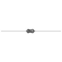
... For technical questions, contact: magnetics@vishay.com Vishay Dale C (Max.) A (Max.) 0.98 [25.0] Min. 1.22 [31.0] B Max. (Max.) A (MAX.) B (MAX.) C (MAX.) 0.236 0.197 0.551 [6.0] [5.0] [14.0] DCR MAX. RATED DC CURRENT () (mA ...

Page 2

... IRF-46 Inductors, Epoxy Conformal Coated, Axial Leaded Vishay Dale ORDERING INFORMATION IRF-46 15 000 μH MODEL INDUCTANCE VALUE GLOBAL PART NUMBER MODEL www.vishay.com 2 ± INDUCTANCE TOLERANCE PACKAGE CODE PACKAGE CODE For technical questions, contact: magnetics@vishay.com e3 JEDEC LEAD (Pb)-FREE STANDARD INDUCTANCE INDUCTANCE VALUE ...

Page 3

... Vishay product could result in personal injury or death. Customers using or selling Vishay products not expressly indicated for use in such applications their own risk and agree to fully indemnify and hold Vishay and its distributors harmless from and against any and all claims, liabilities, expenses and damages arising or resulting in connection with such use or sale, including attorneys fees, even if such claim alleges that Vishay or its distributor was negligent regarding the design or manufacture of the part ...

Related keywords