102692-3 TE Connectivity, 102692-3 Datasheet - Page 305
102692-3
Manufacturer Part Number
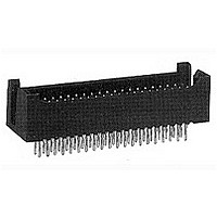
102692-3
Description
Conn Shrouded Header HDR 36 POS 2.54mm Solder ST Thru-Hole
Manufacturer
TE Connectivity
Type
Shrouded Headerr
Datasheet
1.1-102618-8.pdf
(320 pages)
Specifications of 102692-3
Pitch
2.54 mm
Number Of Rows
2
Number Of Contacts
36
Gender
HDR
Contact Plating
Gold Over Nickel
Termination Method
Solder
Connector Type
Header
Pcb Mount Retention
Without
Pcb Mounting Orientation
Vertical
Termination Method To Pc Board
Through Hole - Solder
Post Size (mm [in])
0.64 [.025]
Contact - Rated Current (a)
3
Voltage (vac)
250
Dielectric Withstanding Voltage (v)
750
Termination Resistance (m?)
12
Insulation Resistance (m?)
1,000
Termination Post Length (mm [in])
4.57 [0.180]
Termination End Plating
Tin-Lead over Nickel
Header Type
Standard
Centerline (mm [in])
2.54 [0.100]
Number Of Positions
36
Row-to-row Spacing (mm [in])
2.54 [0.100]
Mating Retention
Without
Contact Protection
With
Contact Protection Type
Shrouded
Assembly Process Feature
None
Contact Type
Pin
Contact Plating, Mating Area, Material
Gold (30)
Contact Shape
Square
Contact Base Material
Phosphor Bronze
Connector Style
Plug
Mating Alignment
With
Mating Alignment Type
Guide Pin
Housing Material
Thermoplastic - GF
Housing Color
Black
Ul Flammability Rating
UL 94V-0
Rohs/elv Compliance
ELV compliant, 5 of 6 Compliant
Lead Free Solder Processes
Wave solder capable to 240°C
Approved Standards
UL E28476, CSA LR7189
Pcb Thickness, Recommended (mm [in])
1.40 [0.055]
Temperature Range (°c)
-65 – +105
Contact Transmits (typical Application)
Signal (Data)


Catalog 1307819
Revised 8-08
www.tycoelectronics.com
The electrical, mechanical
and environmental charac-
teristics of the AMPMODU
.031 x .062 [0.79 x 1.57]
Interconnection System are
listed below:
are metric equivalents.
Dimensions are in inches and
millimeters unless otherwise
specified. Values in brackets
AMPMODU Interconnection System
Performance Specifications
Mechanical Characteristics
Contact Durability
Electrical Characteristics
Contact Current Rating —
5 amperes max. for single contact in free
air, could vary due to ambient tempera-
ture, wire size and duty cycles.
Contact Resistance —
12 milliohms at 100 ma and 50 mv open
circuit.
Dielectric Rating —
At Sea Level – 1200 VAC between con-
tacts on .156 [3.96] centers for 1 minute.
Insulation Resistance — 5 x 10
megohms (initial)
Technical Documents
Various technical docu-
ments are available for your
use:
Product Specifications
describe technical perform-
ance characteristics and
verification tests. They are
intended for the Design,
Component and Quality
Engineer.
108-25016 Interconnection System,
108-25025 Interconnection System,
108-25025-1 Interconnection System,
108-36029 Locking Clip Connectors
Note: All part numbers are RoHS compliant.
Plating
.000016 [0.00041] Min. Tin
.000079 [0.00201] Min. Tin
.000100 [0.00254] Min. Tin
.000015 [0.00038] Gold
.000030 [0.00076] Gold
Standard Pressure
High Pressure, Gold
High Pressure, Tin
Dimensions are shown for
reference purposes only.
Specifications subject
to change.
3
Connector Durability
Receptacles
Mating
Unmating – 1 oz. [0.28N] min. per contact after 3 mating cycles (standard pressure)
Locking Clip Contacts
Mating
Unmating – 2 lb. [8.90N] min. per contact after 3 mating cycles
Environmental Characteristics
Operating Temperature — -65°C to 105°C [-85°F to 221°F] (Gold Plated)
-65°C to 60°C [-85°F to 140°F] (Tin Plated)
Application Specifications
describe requirements for
using the product in its
intended application and/or
crimping information.
They are intended for the
Packaging and Design
Engineer and the Machine
Setup Person.
114-25000 Crimp Snap-In Receptacle
114-25004 Board Mount Receptacle
114-25008 Locking Clip Contacts
114-25011 Machine Applied Straight
– 16 oz. [4.45N] max. per contact after 3 mating cycles
–30 oz. [8.34N] max. per contact after 3 mating cycles
(high pressure, gold)
–60 oz. [16.68N] max. per contact after 3 mating cycles (high pressure, tin)
– 4 lb. [17.79N] max. per contact after 3 mating cycles
200 Cycles
75 Cycles
75 Cycles
75 Cycles
Standard
Pressure
(standard pressure)
3 oz. [0.83N] min. per contact after 3 mating cycles (high pressure)
USA: 1-800-522-6752
Canada: 1-905-470-4425
Mexico: 01-800-733-8926
C. America: 52-55-1106-0803
Contacts
Contacts
Posts
N/A
Receptacles
100 Cycles
Pressure
25 Cycles
25 Cycles
50 Cycles
High
N/A
Instruction Sheets provide
instructions for assembling
or applying the product.
They are intended for the
Manufacturing Assembler or
Operator.
408-7308 Clinching Procedures for
408-7411 Suggestions for Wave
408-7594 Tyco Electronics Hand Tool
408-7750 Tyco Electronics Hand Tool
408-7676 AMPMODU Locking Clip
408-7671 Tyco Electronics Hand Tool
408-7678 Tyco Electronics Extraction
408-7981 Clinching Procedures for
408-9451 Tyco Electronics Extraction
South America: 55-11-2103-6000
Hong Kong: 852-2735-1628
Japan: 81-44-844-8013
UK: 44-8706-080-208a
Header Assemblies
Soldering AMPMODU
Receptacles
90274-2 for Crimping
Crimp Snap-In 18-22 AWG
Contacts
90328-1 for Crimping
Crimp Snap-In Contacts
(22-26 AWG)
Connectors and Contacts
90308-1 for Crimping
Locking Clip Contacts
Tool 91104-1 for Locking
Clip Contacts
Receptacle Assemblies
Tool 843473-1 for Crimp
Snap-In Receptacles
25 Cycles
25 Cycles
Contacts
Locking
Clip
N/A
N/A
N/A
305
7
Related parts for 102692-3
Image
Part Number
Description
Manufacturer
Datasheet
Request
R

Part Number:
Description:
12 MODII 2PC HDR DR SHRD
Manufacturer:
TE Connectivity
Datasheet:
Part Number:
Description:
96 MODII 2PC HDR DR SHRD
Manufacturer:
TE Connectivity
Datasheet:

Part Number:
Description:
High Speed / Modular Connectors 30P HEADER ASSY
Manufacturer:
TE Connectivity
Datasheet:

Part Number:
Description:
High Speed / Modular Connectors REC 6X005P R/A LT B-PLANE HS3
Manufacturer:
TE Connectivity
Datasheet:

Part Number:
Description:
High Speed / Modular Connectors 2MM HM RCPT 50P R/A AU
Manufacturer:
TE Connectivity
Datasheet:

Part Number:
Description:
High Speed / Modular Connectors 2MM HM RCPT 50P R/A AU
Manufacturer:
TE Connectivity
Datasheet:


Part Number:
Description:
Manufacturer:
TE Connectivity
Datasheet:


Part Number:
Description:
Manufacturer:
TE Connectivity
Datasheet:

Part Number:
Description:
Manufacturer:
TE Connectivity
Datasheet:

Part Number:
Description:
Manufacturer:
TE Connectivity
Datasheet: