104313-5 TE Connectivity, 104313-5 Datasheet - Page 138
104313-5
Manufacturer Part Number
104313-5
Description
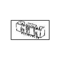
Conn Ejector Header HDR 26 POS 2.54mm Solder ST Thru-Hole
Manufacturer
TE Connectivity
Type
Ejector Headerr
Specifications of 104313-5
Pitch
2.54 mm
Number Of Rows
2
Number Of Contacts
26
Gender
HDR
Contact Plating
Gold
Termination Method
Solder
Pitch (mm)
2.54mm
Number Of Contact Rows
2
Mounting Style
Through Hole
Body Orientation
Straight
Operating Temp Range
-65C to 105C
Current Rating (max)
1/ContactA
Contact Material
Copper Alloy
Housing Material
Thermoplastic
Housing Color
Black
Product Height (mm)
19.53mm
Product Length (mm)
40.64mm
Product Depth (mm)
9.14mm
Width
1.600"
Peak Reflow Compatible (260 C)
No
Terminal Type
Straight PCB Thru Hole
Body Material
Thermoplastic
Leaded Process Compatible
No
Mounting Type
Through Hole
Rohs Compliant
No
Product Line
AMP-LATCH
Profile
Low
Pcb Mounting Orientation
Vertical
Pcb Mount Retention
Without
Mating Connector Lock
Without
Housing Style
4-Sided
Ejection Latches
With
Post Size (mm [in])
0.64 [.025]
Shrouded
Yes
[shrouded] End Dimension (mm [in])
3.81 [0.150]
Current Rating (a)
1
Insulation Resistance (m?)
5,000
Termination Post Length (mm [in])
3.05 [0.120]
Solder Tail Contact Plating
Tin-Lead over Nickel
Header Type
Pin Header
Number Of Positions
26
Centerline, Matrix (mm [in])
2.54 x 2.54 [.100 x .100]
Daisy Chain
With
Preloaded
Yes
Contact Plating, Mating Area, Material
Gold (30)
Contact Shape
Square
Contact Base Material
Copper Alloy
Connector Style
Header - Pin
Mating Alignment Type
Center, Dual Polarizing Bar
Mating Alignment
With
Ul Flammability Rating
UL 94V-0
Rohs/elv Compliance
Not ELV/RoHS compliant
Lead Free Solder Processes
Not suitable for lead free processing
Approved Standards
UL E28476, CSA LR7189
Operating Temperature (°c)
-65 – +105
Temperature Rating
Standard
Lead Free Status / RoHS Status
Not Compliant


Material:
Black polyester
Technical Documents (
The barrier insert can be
used on double row headers
(.100 x .100 [2.54 x 2.54]
centers), including shrouded
versions—3 and 4 sides,
as well as unshrouded
straight post headers. With
one barrier insert several
configurations can be
obtained, providing headers
with capabilities of accepting
various combinations of
polarized and non-polarized
AMPMODU connectors.
For unshrouded headers,
the barrier insert is used to
establish polarization and to
compartmentalize the header.
For shrouded headers, the
barrier insert is used to com-
partmentalize the header,
while maintaining polarization.
The barrier insert itself is
notched to facilitate cutting
off the ends with a simple
tool such as tin snips or
scissors to achieve the
desired configuration.
Catalog 1307819
Catalog 1307819
Catalog 1307819
Revised 6-04
Revised 6-04
Revised 6-04
www.tycoelectronics.com
www.tycoelectronics.com
www.tycoelectronics.com
page 294):
Dimensions are in inches and
Dimensions are in inches and
Dimensions are in inches and
millimeters unless otherwise
millimeters unless otherwise
millimeters unless otherwise
specified. Values in brackets
specified. Values in brackets
specified. Values in brackets
are metric equivalents.
are metric equivalents.
are metric equivalents.
Barrier Insert Cutoffs
Typical Barrier Insert Applications
For Unshrouded Double-Row, Straight Post Headers,
.100 x .100 [2.54 x 2.54] Centers
Note: All configurations of barrier inserts compartmentalize headers and maintain polarization,
For Shrouded Double-Row, 3 and 4 Sided Headers,
.100 x .100 [2.54 x 2.54] Centers
Note: Right-angle (Figs. 2 and 3) and “T” (Fig. 1) configurations of barrier insert establish
AMPMODU Interconnection System
Accessories: Barrier Insert, Part No. 87743-1
[7.98]
.314
(Left and Right Sides)
[0.94]
.037
except bar (Fig. 4) configuration, which is used primarily for compartmentalizing headers.
polarization; bar (Fig. 4) configuration of barrier insert compartmentalizes header.
Partial Cutoff
Fig. 1
See Fig. 2
See Fig. 3
[11.33]
Dimensions are shown for
Dimensions are shown for
Dimensions are shown for
reference purposes only.
reference purposes only.
reference purposes only.
Specifications subject
Specifications subject
Specifications subject
to change.
to change.
to change.
.446
[3.23]
.127
Complete Cutoff
Partial Cutoff
(Right Side)
(Left Side)
Fig. 2
See Fig. 4
See Fig. 4
USA: 1-800-522-6752
USA: 1-800-522-6752
USA: 1-800-522-6752
Canada: 1-905-470-4425
Canada: 1-905-470-4425
Canada: 1-905-470-4425
Mexico: 01-800-733-8926
Mexico: 01-800-733-8926
Mexico: 01-800-733-8926
C. America: 52-55-5-729-0425
C. America: 52-55-5-729-0425
C. America: 52-55-5-729-0425
[8.64]
.340
45°
See Fig. 1
See Fig. 1
Complete Cutoff
Partial Cutoff
(Right Side)
(Left Side)
[0.76]
.030
Fig. 3
[2.29]
.090
[2.54]
South America: 55-11-3611-1514
South America: 55-11-3611-1514
South America: 55-11-3611-1514
Hong Kong: 852-2735-1628
Hong Kong: 852-2735-1628
Hong Kong: 852-2735-1628
Japan: 81-44-844-8013
Japan: 81-44-844-8013
Japan: 81-44-844-8013
UK: 44-141-810-8967
UK: 44-141-810-8967
UK: 44-141-810-8967
.100
[2.21]
[1.19]
.087
.047
(Left and Right Sides)
See Fig. 2
Complete Cutoff
See Fig. 3
Fig. 4
Thru Typ. (2)
Dia. x . 2 5
[ 0 . 7 4 ± 0 . 0 3 ]
[ 0 . 7 9 - 1 . 0 9 ]
r e m a i n d e r
. 0 2 9 ± . 0 0 1
. 0 3 1 - . 0 4 3
[0.76]
D e e p —
.030
D i a .
[2.39]
.094
[ 6 . 3 5 ]
0[
221
5
Related parts for 104313-5
Image
Part Number
Description
Manufacturer
Datasheet
Request
R

Part Number:
Description:
Conn Ejector Header HDR 10 POS 2.54mm Solder ST Thru-Hole
Manufacturer:
TE Connectivity
Datasheet:

Part Number:
Description:
Conn Ejector Header HDR 16 POS 2.54mm Solder ST Thru-Hole
Manufacturer:
TE Connectivity
Datasheet:
Part Number:
Description:
Conn Ejector Header HDR 14 POS 2.54mm Solder ST Thru-Hole
Manufacturer:
TE Connectivity
Datasheet:
Part Number:
Description:
Conn Ejector Header HDR 20 POS 2.54mm Solder ST Thru-Hole
Manufacturer:
TE Connectivity
Datasheet:

Part Number:
Description:
Conn Ejector Header HDR 34 POS 2.54mm Solder ST Thru-Hole
Manufacturer:
TE Connectivity
Datasheet:

Part Number:
Description:
High Speed / Modular Connectors 30P HEADER ASSY
Manufacturer:
TE Connectivity
Datasheet:

Part Number:
Description:
High Speed / Modular Connectors REC 6X005P R/A LT B-PLANE HS3
Manufacturer:
TE Connectivity
Datasheet:

Part Number:
Description:
High Speed / Modular Connectors 2MM HM RCPT 50P R/A AU
Manufacturer:
TE Connectivity
Datasheet:

Part Number:
Description:
High Speed / Modular Connectors 2MM HM RCPT 50P R/A AU
Manufacturer:
TE Connectivity
Datasheet:


Part Number:
Description:
Manufacturer:
TE Connectivity
Datasheet:


Part Number:
Description:
Manufacturer:
TE Connectivity
Datasheet:

Part Number:
Description:
Manufacturer:
TE Connectivity
Datasheet:

Part Number:
Description:
Manufacturer:
TE Connectivity
Datasheet: