1-102618-1 TE Connectivity, 1-102618-1 Datasheet - Page 225
1-102618-1
Manufacturer Part Number
1-102618-1
Description
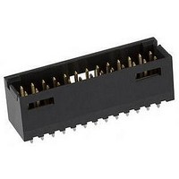
Conn Shrouded Header HDR 26 POS 2.54mm Solder ST Thru-Hole
Manufacturer
TE Connectivity
Type
Shrouded Headerr
Series
AMPMODU Mod IIr
Datasheet
1.1-102618-8.pdf
(320 pages)
Specifications of 1-102618-1
Pitch
2.54 mm
Number Of Rows
2
Number Of Contacts
26
Gender
HDR
Contact Plating
Gold Over Nickel
Termination Method
Solder
Connector Type
Wire To Board
Contact Termination
Through Hole
No. Of Contacts
26
No. Of Rows
2
Pitch Spacing
2.54mm
Rohs Compliant
No
Product Type
Connector
[shrouded] End Dimension (mm [in])
1.68 [0.066]
Mount Angle
Vertical
Pcb Mount Retention
Without
Surface Mount Compatible
No
Board Standoff
Without
Mounting Ears
Without
Mating Connector Lock
With
Mating Connector Lock Type
Detent Windows
Housing Style
4-Sided
Post Size (mm [in])
0.64 [.025]
Profile
Standard
Mating Post Length (mm [in])
8.08 [0.318]
Panel Mount Retention
Without
Current Rating (a)
3
Insulation Resistance (m?)
5,000
Dielectric Withstanding Voltage (v)
750
Termination Post Length (mm [in])
3.18 [0.125]
Solder Tail Contact Plating
Tin-Lead over Nickel
Header Type
Shrouded
Number Of Positions
26
Centerline (mm [in])
2.54 [0.100]
Row-to-row Spacing (mm [in])
2.54 [0.100]
Selectively Loaded
No
Mount Type
Printed Circuit Board
Contact Plating, Mating Area, Material
Gold (15)
Contact Shape
Square
Contact Base Material
Phosphor Bronze
Housing Material
Thermoplastic - GF
Housing Color
Black
Ul Flammability Rating
UL 94V-0
Rohs/elv Compliance
Not ELV/RoHS compliant
Lead Free Solder Processes
Wave solder capable to 240°C
Approved Standards
UL E28476, CSA LR7189
Operating Temperature (°c)
-55 – +105
High Temperature Housing
No
High Speed Serial Data Connector
No


Product Facts
■
■
■
■
■
■
■
■
■
■
■
■
■
■
■
Catalog 1307819
Revised 8-08
www.tycoelectronics.com
Receptacle assemblies mate
with .025 [0.64] sq. posts;
mating post length is .200
[5.08] min., .250 [6.35] max.
Proven AMPMODU receptacle
contact design; dual
cantilever beams, built-in
anti-overstress, completely
enclosed “box” design,
standard or high-pressure
Insulation displacement
technology
Two contact sizes for
terminating 30-22 AWG [0.05-
0.3 mm
[1.37] max. insulation diam -
eter with an insulation wall
thickness of .015 [0.38] max.
Choice of gold duplex or tin
plated contacts
Interchangeable crimp
snap-in pin and receptacle
contacts available
Housing sizes 2 through
25 positions, single-row .100
[2.54] centers
Plain housings are end-to-end
and/or back-to-back stackable
for open pin field applications
Optional header with
“swaged tail” feature helps
prevent movement prior to
flow soldering
Integral latch provides
positive retention between
header and receptacle
housing
Coupling shrouds permit
ganging of smaller connectors
with guide ribs to form larger
single- or double-row
latching connectors
Mass terminating tooling
provides lowest applied cost
for most production needs
SMT and SMT compatible,
high-temp headers available
Recognized under the
Component Program of
Underwriters
Laboratories Inc.,
File No. E28476
Certified by Canadian
Standards
Association,
File No. LR7189
2
] wire range; .054
R
are metric equivalents.
Dimensions are in inches and
millimeters unless otherwise
specified. Values in brackets
R
AMPMODU Interconnection System
MTE Interconnection System
The AMPMODU MTE
Interconnection System
offers both wire-to-board
and wire-to-wire connectors
using .025 [0.64] sq. post
technology.
The AMPMODU MTE
Interconnection System
consists of single-row
housings with contacts
preloaded on .100 [2.54]
centers. Housings are
furnished with contacts
partially inserted, leaving
the termination areas
exposed. Final contact
insertion can be
accomplished automatically
with Tyco Electronics
application equipment, and
manually when terminated
with the Tyco Electronics
pistol grip hand tool.
The heart of the system is
the insulation displacement
contact design, featured in
both pin and receptacle
contacts. The receptacle
Dimensions are shown for
reference purposes only.
Specifications subject
to change.
contact, available in either
standard or high-pressure,
features dual cantilever
beams in an enclosed
“box.” The post stop helps
prevent a mating post from
disturbing the wire
termination and also limits
the mating depth of a long
post to protect a wrap-type
termination at the base of
the post. The forward
contact stop helps prevent
contact overinsertion prior
to termination. All contacts
are furnished on carrier
strips which are interlocked
for stability and positive
location during termination.
Single-row housings are
available in sizes 2 through
25 positions. Included are
three styles of receptacle
housings—plain, polarized/
latching and ribbed and two
styles of pin housings,
shrouded with polarizing/
latching feature and ribbed.
USA: 1-800-522-6752
Canada: 1-905-470-4425
Mexico: 01-800-733-8926
C. America: 52-55-1106-0803
Performance
Specifications
Electrical Characteristics
Contact Current Rating —
3 amperes for single contact in free air
(Amperage could vary due to ambient
temperature, wire size and duty cycles.)
Contact Termination
Resistance — 15 milliohms (max.)
Dielectric Withstanding Voltage —
At Sea Level–600 VAC, rms
At 70,000 Ft. [21 336 m]–225 VAC, rms
Insulation Resistance —
5,000 megohms (min.)
Environmental Characteristics
Operating Temperature —
-65°C to +105°C
Vibration — 15 G’s (gold), 10 G’s (tin)
Physical Shock — 50 G’s
Industrial Mixed Flow Gasing —
Class 1 (20 days) (gold)
Product Specification
108-25034
Application Specification
114-25026
South America: 55-11-2103-6000
Hong Kong: 852-2735-1628
Japan: 81-44-844-8013
UK: 44-8706-080-208
225
5
Related parts for 1-102618-1
Image
Part Number
Description
Manufacturer
Datasheet
Request
R

Part Number:
Description:
Conn Wire to Board HDR 10 POS 2.54mm Solder ST Thru-Hole
Manufacturer:
TE Connectivity
Datasheet:

Part Number:
Description:
Conn Shrouded Header HDR 10 POS 2mm Solder ST Thru-Hole
Manufacturer:
TE Connectivity
Datasheet:

Part Number:
Description:
Conn Wire to Board HDR 10 POS 2.54mm Solder RA Thru-Hole
Manufacturer:
TE Connectivity
Datasheet:

Part Number:
Description:
Conn IDC Connector PL 10 POS 2.54mm IDT RA Cable Mount Bulk
Manufacturer:
TE Connectivity
Datasheet:

Part Number:
Description:
TIMER, CONNECTOR HOUSING, 10 POS
Manufacturer:
TE Connectivity
Datasheet:

Part Number:
Description:
Manufacturer:
TE Connectivity
Datasheet:

Part Number:
Description:
Manufacturer:
TE Connectivity
Datasheet:

Part Number:
Description:
Manufacturer:
TE Connectivity
Datasheet:

Part Number:
Description:
Manufacturer:
TE Connectivity
Datasheet:

Part Number:
Description:
Manufacturer:
TE Connectivity
Datasheet:

Part Number:
Description:
Manufacturer:
TE Connectivity
Datasheet:

Part Number:
Description:
Manufacturer:
TE Connectivity
Datasheet:

Part Number:
Description:
Manufacturer:
TE Connectivity
Datasheet:

Part Number:
Description:
Manufacturer:
TE Connectivity
Datasheet:

Part Number:
Description:
Manufacturer:
TE Connectivity
Datasheet: