1-532955-5 TE Connectivity, 1-532955-5 Datasheet - Page 204
1-532955-5
Manufacturer Part Number
1-532955-5
Description
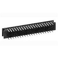
Conn Socket Strip RCP 96 POS 2.54mm Solder RA Thru-Hole
Manufacturer
TE Connectivity
Type
Socket Stripr
Datasheet
1.1-102618-8.pdf
(320 pages)
Specifications of 1-532955-5
Pitch
2.54 mm
Number Of Rows
2
Number Of Contacts
96
Gender
RCP
Contact Plating
Gold Over Nickel
Termination Method
Solder
Rohs Compliant
NO
Product Type
Receptacles / Sockets - PCB
Contact Gender
Socket (Female)
Number Of Positions / Contacts
96
Row Spacing
2.54 mm
Mounting Style
Through Hole
Mounting Angle
Right
Termination Style
Solder
Housing Material
Thermoplastic, Glass Filled
Contact Material
Phosphor Bronze
Voltage Rating
250 VAC
Current Rating
3 A
Operating Temperature Range
- 65 C to + 105 C
Connector Type
Connector Assembly
Pcb Mount Retention
Without
Pcb Mounting Orientation
Right Angle
Termination Method To Pc Board
Through Hole - Solder
Contact - Rated Current (a)
3
Voltage (vac)
250
Dielectric Withstanding Voltage (v)
750
Termination Resistance (m?)
12
Insulation Resistance (m?)
1,000
Termination Post Length (mm [in])
2.92 [0.115]
Termination End Plating
Tin-Lead over Nickel
Centerline (mm [in])
2.54 [0.100]
Number Of Positions
96
Row-to-row Spacing (mm [in])
2.54 [0.100]
Mating Retention
Without
Assembly Process Feature
Board Standoff
Contact Type
Socket
Contact Plating, Mating Area, Material
Gold (15)
Contact Base Material
Phosphor Bronze
Connector Style
Receptacle
Mating Alignment
With
Mating Alignment Type
Guide Pin Slot
Housing Color
Black
Ul Flammability Rating
UL 94V-0
Rohs/elv Compliance
Not ELV/RoHS compliant
Lead Free Solder Processes
Wave solder capable to 240°C, Wave solder capable to 260°C, Wave solder capable to 265°C
Approved Standards
UL E28476, CSA LR7189
Pcb Thickness, Recommended (mm [in])
1.57 [0.062]
High Temperature Compatible
Yes
Temperature Range (°c)
-65 – +105
Contact Transmits (typical Application)
Signal (Data)
Lead Free Status / Rohs Status
No
Available stocks
Company
Part Number
Manufacturer
Quantity
Price
Company:

Part Number:
1-532955-5
Manufacturer:
TE Connectivity AMP Connectors
Quantity:
78


5
204
Material
Black polyester
Technical Documents
The barrier insert can be
used on double row headers
(.100 x .100 [2.54 x 2.54]
centers), including shrouded
versions—3 and 4 sides,
as well as unshrouded
straight post headers. With
one barrier insert several
configurations can be
obtained, providing headers
with capabilities of accept-
ing various combinations of
polarized and non-polarized
AMPMODU connectors.
For unshrouded headers,
the barrier insert is used
to establish polarization
and to compartmentalize
the header. For shrouded
headers, the barrier insert is
used to compartmentalize
the header, while maintaining
polarization. The barrier
insert itself is notched to
facilitate cutting off the
ends with a simple tool
such as tin snips or scissors
to achieve the desired
configuration.
Catalog 1307819
Revised 8-08
www.tycoelectronics.com
— page 276
are metric equivalents.
Dimensions are in inches and
millimeters unless otherwise
specified. Values in brackets
AMPMODU Interconnection System
Accessories: Barrier Insert, Part No. 87743-1
Barrier Insert Cutoffs
Typical Barrier Insert Applications
For Unshrouded Double-Row, Straight Post Headers,
.100 x .100 [2.54 x 2.54] Centers
Note: All configurations of barrier inserts compartmentalize headers and maintain polarization,
For Shrouded Double-Row, 3 and 4 Sided Headers,
.100 x .100 [2.54 x 2.54] Centers
Note: Right-angle (Figs. 2 and 3) and “T” (Fig. 1) configurations of barrier insert establish
Note: All part numbers are RoHS compliant.
[7.98]
.314
(Left and Right Sides)
[0.94]
.037
Partial Cutoff
except bar (Fig. 4) configuration, which is used primarily for compartmentalizing headers.
polarization; bar (Fig. 4) configuration of barrier insert compartmentalizes header.
Fig. 1
See Fig. 2
See Fig. 3
[11.33]
Dimensions are shown for
reference purposes only.
Specifications subject
to change.
.446
[3.23]
.127
Complete Cutoff
Partial Cutoff
(Right Side)
(Left Side)
Fig. 2
See Fig. 4
See Fig. 4
USA: 1-800-522-6752
Canada: 1-905-470-4425
Mexico: 01-800-733-8926
C. America: 52-55-1106-0803
[8.64]
.340
45°
See Fig. 1
See Fig. 1
Complete Cutoff
Partial Cutoff
(Right Side)
(Left Side)
[0.76]
.030
Fig. 3
[2.29]
.090
[2.54]
South America: 55-11-2103-6000
Hong Kong: 852-2735-1628
Japan: 81-44-844-8013
UK: 44-8706-080-208
.100
[2.21]
[1.19]
.087
.047
(Left and Right Sides)
See Fig. 2
Complete Cutoff
See Fig. 3
Fig. 4
Thru Typ. (2)
[0.74±0.03]
Dia. x
[0.79-1.09]
remainder
.029±.001
.031-.043
[0.76]
Deep—
.030
Dia.
[2.39]
.094
[6.35]
.250[
Related parts for 1-532955-5
Image
Part Number
Description
Manufacturer
Datasheet
Request
R

Part Number:
Description:
Lamps 14.4V .12A
Manufacturer:
CHICAGO MINIATURE LIGHTING, LLC
Datasheet:

Part Number:
Description:
Manufacturer:
TE Connectivity
Datasheet:

Part Number:
Description:
53 1MA HP
Manufacturer:
Tyco Electronics
Datasheet:

Part Number:
Description:
53 10KC HP
Manufacturer:
Tyco Electronics
Datasheet:

Part Number:
Description:
Plug And Socket Connector Housing
Manufacturer:
TE Connectivity
Datasheet:

Part Number:
Description:
Conn Wire to Board HDR 15 POS 2.54mm Solder ST Thru-Hole
Manufacturer:
TE Connectivity
Datasheet:

Part Number:
Description:
Manufacturer:
TE Connectivity
Datasheet:

Part Number:
Description:
DYNAMIC D-3200 HDR ASSY 5P V
Manufacturer:
TE Connectivity
Datasheet:

Part Number:
Description:
Manufacturer:
TE Connectivity
Datasheet:

Part Number:
Description:
CONTACT, RECEPTACLE, 20-16AWG, CRIMP
Manufacturer:
TE Connectivity
Datasheet:

Part Number:
Description:
DIP SOCKET, 40POS, THROUGH HOLE
Manufacturer:
TE Connectivity
Datasheet:

Part Number:
Description:
DIP SOCKET, 18POS, THROUGH HOLE
Manufacturer:
TE Connectivity
Datasheet:

Part Number:
Description:
PLCC SOCKET, 52POS, THROUGH HOLE
Manufacturer:
TE Connectivity
Datasheet:
Part Number:
Description:
Manufacturer:
TE Connectivity
Datasheet: