1-534998-3 TE Connectivity, 1-534998-3 Datasheet - Page 104
1-534998-3
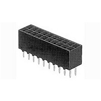
Manufacturer Part Number
1-534998-3
Description
Conn Socket Strip RCP 26 POS 2.54mm Solder ST Thru-Hole Gang of Tubes
Manufacturer
TE Connectivity
Type
Socket Stripr
Datasheet
1.1-102618-8.pdf
(320 pages)
Specifications of 1-534998-3
Pitch
2.54 mm
Number Of Rows
2
Number Of Contacts
26
Gender
RCP
Contact Plating
Gold Over Nickel
Termination Method
Solder
Product Type
Connector
Connector Series
Mod IV
Profile
Low
Mounting Pattern (mm [in])
2.54 x 2.54 [.100 x .100]
Sealed
No
Holddown Feature
Without
Pcb Mounting Orientation
Vertical
Pcb Mount Retention
With
Termination Method To Pc Board
Through Hole - Solder
Closed Entry
With
Board Standoff
With
Stackable
Yes
Contact - Rated Current (a)
2
Contact Resistance (m?)
12
Insulation Resistance (m?)
5,000
Dielectric Withstanding Voltage (v)
750
Termination Post Length (mm [in])
3.18 [0.125]
Solder Tail Contact Plating
Tin-Lead over Nickel
Connector Height (mm [in])
6.22 [0.245]
Number Of Positions
26
Centerline, Matrix (mm [in])
2.54 x 2.54 [.100 x .100]
Pcb Mount Retention Type
Retention Solder Tails
Contact Plating, Mating Area, Material
Gold (30)
Contact Base Material
Phosphor Bronze
Housing Entry Style
Top
Housing Material
Polyester PCT
Ul Flammability Rating
UL 94V-0
Housing Color
Black
Government/industry Qualification
No
Rohs/elv Compliance
ELV compliant, 5 of 6 Compliant
Lead Free Solder Processes
Wave solder capable to 240°C
Approved Standards
UL E28476, CSA LR7189
Operating Temperature (°c)
-65 – +105
Pcb Thickness, Recommended (mm [in])
1.57 [0.062]
High Temperature Compatible
No
Packaging Method
Gang of Tubes
Available stocks
Company
Part Number
Manufacturer
Quantity
Price
Company:

Part Number:
1-534998-3
Manufacturer:
TE Connectivity AMP Connectors
Quantity:
459


5
104
.025 [0.64] Square
Straight Posts
Material and Finish
Housing — Black thermoplastic, 94V-0
rated, high temperature compatible
Posts — Phosphor bronze, plated as
follows:
Plating A — Duplex plated .000030
[0.00076] gold on contact area,
.000100-.000200 [0.00254-0.00508]
tin on solder tail, with entire post
underplated .000050 [0.00127] nickel
Plating B — Duplex plated .000015
[0.00038] gold on contact area,
.000100-.000200 [0.00254-0.00508]
tin on solder tail, with entire post
underplated .000050 [0.00127] nickel
Plating C — .000100-.000200
[0.00254-0.00508] tin over
.000050 [0.00127] nickel
Performance Characteristics
(Board Retention Tails)
Insertion Force — 12 lb [53.4N] max.
Retention Force — .25 lb [1.11N] min.
Related Product Data
Mateable Connectors —
Refer to the Mating Post Selection
Guide — page 90
Technical Documents
See mating connector for applicable
product and application specifications.
Notes: 1. Headers without retention tails may be broken to the desired number of positions using Tool Kit No. 314818-1 (not shown).
Catalog 1307819
Revised 8-08
www.tycoelectronics.com
Retention Tails
(See Note 2.)
Solder Tails
(See Notes
With Board
1 and 2.)
Header
Style
With
2. Headers are also available in sizes 4 thru 78 positions. When ordering, add the prefix and/or suffix (dash) numbers plus 5- -0 to the base part number that corresponds with the
number of positions per row. For example, the complete part number for a 16-position header with solder tails (C dimension .090 [2.29], post plating A) would be 5-146261-8.
The complete part number for a 40-position header with board retention tails (C dimension .120 [3.05], post plating B) would be 7-146268-0. This part numbering system
applies only to this page.
No. of
Pos.
80
80
2
2
— page 276
3.984 [101.19]
3.984 [101.19]
.084 [2.13]
.084 [2.13]
are metric equivalents.
Dimensions are in inches and
millimeters unless otherwise
specified. Values in brackets
A
Dimensions
3.900 [99.06]
3.900 [99.06]
AMPMODU Interconnection System
Breakaway Headers—Unshrouded, Double-Row,
.100 x .100 [2.54 x 2.54] Centerline
Headers with Board Retention Tails
Note: All part numbers are RoHS compliant.
Headers with Solder Tails
*±.003 [±0.08] tolerances not to accumulate within one connector pattern.
(
*±.003 [±0.08] tolerances not to accumulate within one connector pattern.
(
—
—
C L
B
C L
of Hole Pattern)
of Hole Pattern)
[2.54]
[2.54]
.100
.100
(for .062 [1.57] thick PC board; .008 [.203] thick stencil)
(for .062 [1.57] thick PC board; .008 [.203] thick stencil)
[0.64]
[0.64]
.025
Typ.
.025
Typ.
5-146261-1 5-146260-1 5-146258-1 5-146257-1 5-146256-1 5-146254-1 5-146253-1 5-146252-1 5-146250-1
9-146261-0 9-146260-0 9-146258-0 9-146257-0 9-146256-0 9-146254-0 9-146253-0 9-146252-0 9-146250-0
5-146273-1 5-146272-1 5-146270-1 5-146269-1 5-146268-1 5-146266-1 5-146265-1 5-146264-1 5-146262-1
9-146273-0 9-146272-0 9-146270-0 9-146269-0 9-146268-0 9-146266-0 9-146265-0 9-146264-0 9-146262-0
Plating A
Recommended PC Board Mounting Pattern
Recommended PC Board Mounting Pattern
Post Plating/Part Nos.
Dimensions are shown for
reference purposes only.
Specifications subject
to change.
C = .090 [2.29]
D = .230 [5.84]
E = .185 [4.70]
[3.81±0.05]
Plating B
.150±.002
[2.29±0.05]
.090±.002
[2.54]
.100*
.100*
[2.54]
Plating C
[0.76±0.05]
[0.76±0.05]
A
B
.030±.002
.030±.002
B
A
Plating A
USA: 1-800-522-6752
Canada: 1-905-470-4425
Mexico: 01-800-733-8926
C. America: 52-55-1106-0803
Post Plating/Part Nos.
C = .120 [3.05]
D = .230 [5.84]
E = .185 [4.70]
Plating B
[1.14]
[1.91]
.045
.075
Ref.
Ref.
Plating C
(
(
C L
C L
C
of Stencil Pattern)
of Stencil Pattern)
Recommended Hole Size
Recommended Hole Size
[0.89±0.08]
[1.14±0.02]
C
[1.02±0.08]
[1.14±0.02]
[2.79]
.035±.003
.045±.001
.040±.003
.045±.001
D
[4.32]
.110
.170
Before Plating
Before Plating
[2.54]
.100
Plating A
(Plated)
(Plated)
D
South America: 55-11-2103-6000
Hong Kong: 852-2735-1628
Japan: 81-44-844-8013
UK: 44-8706-080-208
Dia. Typ.
Dia. Typ.
Dia. Typ.
Dia. Typ.
Post Plating/Part Nos.
C = .125 [3.18]
D = .318 [8.08]
E = .200 [5.08]
[4.88]
.192
Plating B
[4.88]
.192
(Contact Area)
(Contact Area)
E Ref.
Plating C
E Ref.
[2.29]
.090
[2.29]
.090
Related parts for 1-534998-3
Image
Part Number
Description
Manufacturer
Datasheet
Request
R

Part Number:
Description:
Lamps 14.4V .12A
Manufacturer:
CHICAGO MINIATURE LIGHTING, LLC
Datasheet:

Part Number:
Description:
Manufacturer:
TE Connectivity
Datasheet:

Part Number:
Description:
53 1MA HP
Manufacturer:
Tyco Electronics
Datasheet:

Part Number:
Description:
53 10KC HP
Manufacturer:
Tyco Electronics
Datasheet:

Part Number:
Description:
Plug And Socket Connector Housing
Manufacturer:
TE Connectivity
Datasheet:

Part Number:
Description:
Conn Wire to Board HDR 15 POS 2.54mm Solder ST Thru-Hole
Manufacturer:
TE Connectivity
Datasheet:

Part Number:
Description:
Manufacturer:
TE Connectivity
Datasheet:

Part Number:
Description:
DYNAMIC D-3200 HDR ASSY 5P V
Manufacturer:
TE Connectivity
Datasheet:

Part Number:
Description:
Manufacturer:
TE Connectivity
Datasheet:

Part Number:
Description:
CONTACT, RECEPTACLE, 20-16AWG, CRIMP
Manufacturer:
TE Connectivity
Datasheet:

Part Number:
Description:
DIP SOCKET, 40POS, THROUGH HOLE
Manufacturer:
TE Connectivity
Datasheet:

Part Number:
Description:
DIP SOCKET, 18POS, THROUGH HOLE
Manufacturer:
TE Connectivity
Datasheet:

Part Number:
Description:
PLCC SOCKET, 52POS, THROUGH HOLE
Manufacturer:
TE Connectivity
Datasheet:
Part Number:
Description:
Manufacturer:
TE Connectivity
Datasheet: