102898-1 TE Connectivity, 102898-1 Datasheet - Page 23
102898-1
Manufacturer Part Number
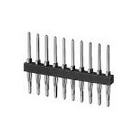
102898-1
Description
Conn Unshrouded Header HDR 8 POS 2.54mm Press Fit ST Thru-Hole
Manufacturer
TE Connectivity
Type
Unshrouded Headerr
Datasheet
1.102898-1.pdf
(236 pages)
Specifications of 102898-1
Pitch
2.54 mm
Number Of Rows
1
Number Of Contacts
8
Gender
HDR
Contact Plating
Gold Over Nickel
Termination Method
Press Fit
Product Type
Connector
Mount Angle
Vertical
Pcb Mount Retention
With
Surface Mount Compatible
No
Board Standoff
Without
Mounting Ears
Without
Mating Connector Lock
Without
Post Size (mm [in])
0.64 [.025]
Mating Post Length (mm [in])
8.13 [0.320]
Panel Mount Retention
Without
Current Rating (a)
3
Insulation Resistance (m?)
5,000
Dielectric Withstanding Voltage (v)
750
Termination Post Length (mm [in])
6.35 [0.250]
Solder Tail Contact Plating
Tin-Lead over Nickel
Header Type
Standard
Number Of Positions
8
Centerline (mm [in])
2.54 [0.100]
Row-to-row Spacing (mm [in])
2.54 [0.100]
Selectively Loaded
No
Pcb Mount Retention Type
Compliant Posts
Mount Type
Printed Circuit Board
Contact Plating, Mating Area, Material
Gold (30)
Contact Shape
Square
Contact Base Material
Copper-Nickel-Tin
Housing Material
Thermoplastic - GF
Housing Color
Black
Ul Flammability Rating
UL 94V-0
Rohs/elv Compliance
RoHS compliant, ELV compliant
Lead Free Solder Processes
Not relevant for lead free process
Rohs/elv Compliance History
Always was RoHS compliant
Approved Standards
UL E28476, CSA LR7189
Operating Temperature (°c)
-55 – +125
High Temperature Housing
No
Pcb Thickness, Recommended (mm [in])
2.36 – 3.18 [0.093 – 0.125]
High Speed Serial Data Connector
No


HTS Industrie Steckverbinder
Verbindlich für Toleranzen der Abmessungen und technische Werte sind ausschließlich die neuesten Tyco Electronics Kundenzeichnungen bzw. Produkt-Spezifikationen, die Sie auf Anfrage erhalten.
All specifications subject to change. Consult Tyco Electronics for latest design specifications.
Insulation Coordination for Electrical Connectors in Low Voltage Plants
Dimensioning of Clearance and Creeping Distances acc. to DIN EN60664-1; following pages show only a part of the standards
Insulation Coordination
Insulation coordination includes the design of the electrical insulation of a connector depending on its use and environment.
This occurs either by design of the clearance distances (basis is the expected power surge) or by design of the creeping distance (basis
is the operating voltage as well as the quality of the insulating material). Furthermore, insulation-changing conditions are taken into
account (pollution, protective measures against pollution, air pressure, thermal or chemical influences).
Air distances are measured according to the outer or inner power surge expected. The four power surge classes (power surge catego-
ries I to IV) take the different use of the connector into account.
Depending on the homogeneity of the field between the electrodes (case A – inhomogenous field, case B – homogenous field) the air
distances can be determined according to table 2a (minimum air distances); industrial connectors are always determined according to
case A.
The influence from pollution when determining the air- and creeping distances is taken into account by using four degrees of severity
(pollution degree 1 to 4).
Basis of the creeping distances is the rated voltage which is deduced from the operating voltage.
The minimum creeping distances are allocated in table 4 depending on the severity of pollution.
If the product descriptions do not contain any additional information the products listed in this catalogue were rated according to norm
DIN VDE 0110 for surge category III and severity of pollution 3.
Surge Category I to IV
• resources of surge category I are goods for the termination of fixed electrical installations of a building. Measures for the limitation of
• resources of surge category II are resources which use power and are fed from a fixed installation.
• resources of surge category III are part of a fixed installation. They are resources from which a high degree of availability is
• Devices of surge category IV are for use at the supply terminal of the installation.
Pollution Degree 1 to 4
DIN VDE 0110 defines the pollution degrees as follows: :
Pollution Degree 1:
There is no or only dry, non-conductive pollution. The pollution is without influence.
Pollution Degree 2:
There is only non-conductive pollution. Occasional momentary conductivity due to condensation.
Pollution Degree 3:
There is conductive pollution or dry non-conductive pollution, which becomes conductive due to condensation.
Pollution Degree 4:
There is a continuous conductivity due to conductive dust, rain or moisture.
Insulation Material
The insulation materials are divided into the following four groups depending on their comparative tracking index (CTI) :
Insulation material I:
Insulation material II:
Insulation material III a:
transient surges were taken either in the fixed installation or between the fixed installation and the equipment.
Note: e. g. domestic applicances, portable tools and other appliances as well as similar consumers.
expected.
Note: Examples for such appliances are e.g. industrial connectors, distribution panels, power switches, distributors, switches, sockets).
Note: Examples for such appliances are electricity counters, overload cut-out switches and Rundsteuergeräte.
600
400
175
CTI
CTI < 600
CTI < 400
HTS Heavy Duty Connectors
21
Related parts for 102898-1
Image
Part Number
Description
Manufacturer
Datasheet
Request
R


Part Number:
Description:
Printers THERMAL PRINTER HS-SLEEVE MARKER
Manufacturer:
TE Connectivity


Part Number:
Description:
High Speed / Modular Connectors 30P HEADER ASSY
Manufacturer:
TE Connectivity
Datasheet:

Part Number:
Description:
High Speed / Modular Connectors REC 6X005P R/A LT B-PLANE HS3
Manufacturer:
TE Connectivity
Datasheet:

Part Number:
Description:
High Speed / Modular Connectors 2MM HM RCPT 50P R/A AU
Manufacturer:
TE Connectivity
Datasheet:

Part Number:
Description:
High Speed / Modular Connectors 2MM HM RCPT 50P R/A AU
Manufacturer:
TE Connectivity
Datasheet:


Part Number:
Description:
Manufacturer:
TE Connectivity
Datasheet:


Part Number:
Description:
Manufacturer:
TE Connectivity
Datasheet:

Part Number:
Description:
Manufacturer:
TE Connectivity
Datasheet:

Part Number:
Description:
Manufacturer:
TE Connectivity
Datasheet: