103542-4 TE Connectivity, 103542-4 Datasheet - Page 285
103542-4
Manufacturer Part Number
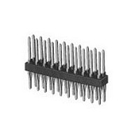
103542-4
Description
Conn Unshrouded Header HDR 10 POS 2.54mm Press Fit ST Thru-Hole
Manufacturer
TE Connectivity
Type
Unshrouded Headerr
Datasheet
1.1-102618-8.pdf
(320 pages)
Specifications of 103542-4
Pitch
2.54 mm
Number Of Rows
2
Number Of Contacts
10
Gender
HDR
Contact Plating
Gold Over Nickel
Termination Method
Press Fit
Product Type
Connector
Mount Angle
Vertical
Pcb Mount Retention
With
Surface Mount Compatible
No
Board Standoff
Without
Mounting Ears
Without
Mating Connector Lock
Without
Post Size (mm [in])
0.64 [.025]
Mating Post Length (mm [in])
8.13 [0.320]
Panel Mount Retention
Without
Termination Post Length (mm [in])
6.35 [0.250]
Solder Tail Contact Plating
Tin-Lead over Nickel
Header Type
Standard
Number Of Positions
10
Centerline (mm [in])
2.54 [0.100]
Row-to-row Spacing (mm [in])
2.54 [0.100]
Selectively Loaded
No
Pcb Mount Retention Type
Compliant Posts
Mount Type
Printed Circuit Board
Contact Plating, Mating Area, Material
Gold (30)
Contact Shape
Square
Contact Base Material
Copper-Nickel-Tin
Housing Material
Thermoplastic - GF
Housing Color
Black
Ul Flammability Rating
UL 94V-0
Rohs/elv Compliance
RoHS compliant, ELV compliant
Lead Free Solder Processes
Not relevant for lead free process
Rohs/elv Compliance History
Always was RoHS compliant
High Temperature Housing
Yes
Pcb Thickness, Recommended (mm [in])
1.57 [0.062]
High Speed Serial Data Connector
No


Vertical and Horizontal
Board Mount
Related Product Data
Recommended Board Layout for
Type C — page 288
Mates with —
Machine Applied Posts — page 294
Headers — pages 295-297
Application Tooling —
pages 300-304
Performance Specifications —
page 305
Technical Documents
page 305
Keying Plug
Catalog 1307819
Revised 8-08
www.tycoelectronics.com
Use in Board Mount Receptacles
Part No. 86181-2
Post Entry
Post Entry
Horizontal
Post Entry
Bottom
Type A
Type B
Type C
Top
—
are metric equivalents.
Dimensions are in inches and
millimeters unless otherwise
specified. Values in brackets
AMPMODU Interconnection System
Mod I Receptacles, Board Mount, .031 x .062 [0.79 x 1.57] Centerline
Receptacle Styles
Recommended Board Layout for Receptacle Assemblies
and Individual Receptacles (Type A and B)
Note: All part numbers are RoHS compliant.
J-Receptacle centers may vary depending on requirements. For individual receptacles, minimum nominal centerline
spacing between adjacent receptacles is .150 [3.81]; for receptacle assemblies, centerline spacing between adjacent
receptacles is .156 [3.96]. The .003 [0.08] tolerances are not to accumulate over length of board. For solder mask, see
Tyco Electronics Instruction Sheet 408-7411.
Note: Drawings depict normal use of the contact in a one or two-sided circuit board. When using plated thru-holes,
refer to Tyco Electronics Engineering Report ER-001 and Tyco Electronics Instruction Sheet 408-7411. For solder
mask, see Tyco Electronics Instruction Sheet 408-7411.
Dimensions are shown for
reference purposes only.
Specifications subject
to change.
[7.62]
.300
[0.99]
.093
Max.
[3.18]
J
.125
[1.40]
[3.18]
.055
Min.
.125
[±0.08]
±.003
Max.
(Post Entry Type A or B)
USA: 1-800-522-6752
Canada: 1-905-470-4425
Mexico: 01-800-733-8926
C. America: 52-55-1106-0803
2J
Round Hole
[±0.08]
±.003
[3.18]
.125
Max.
[2.54]
.100
[3.18±0.05]
.125±.002
Min.
[0.99]
.093
[7.62]
.300
Max.
South America: 55-11-2103-6000
Hong Kong: 852-2735-1628
Japan: 81-44-844-8013
UK: 44-8706-080-208a
[7.62]
.300
[2.36]
.093
Max.
[3.18]
.125
Max.
285
7
Related parts for 103542-4
Image
Part Number
Description
Manufacturer
Datasheet
Request
R

Part Number:
Description:
16 MODII HDR DRST UNSHRD A/PIN
Manufacturer:
TE Connectivity
Datasheet:
Part Number:
Description:
20 MODII HDR DRST UNSHRD A/PIN
Manufacturer:
TE Connectivity
Datasheet:

Part Number:
Description:
Printers THERMAL PRINTER HS-SLEEVE MARKER
Manufacturer:
TE Connectivity


Part Number:
Description:
High Speed / Modular Connectors 30P HEADER ASSY
Manufacturer:
TE Connectivity
Datasheet:

Part Number:
Description:
High Speed / Modular Connectors REC 6X005P R/A LT B-PLANE HS3
Manufacturer:
TE Connectivity
Datasheet:

Part Number:
Description:
High Speed / Modular Connectors 2MM HM RCPT 50P R/A AU
Manufacturer:
TE Connectivity
Datasheet:

Part Number:
Description:
High Speed / Modular Connectors 2MM HM RCPT 50P R/A AU
Manufacturer:
TE Connectivity
Datasheet:


Part Number:
Description:
Manufacturer:
TE Connectivity
Datasheet:


Part Number:
Description:
Manufacturer:
TE Connectivity
Datasheet:

Part Number:
Description:
Manufacturer:
TE Connectivity
Datasheet:

Part Number:
Description:
Manufacturer:
TE Connectivity
Datasheet: