5499206-2 TE Connectivity, 5499206-2 Datasheet - Page 77
5499206-2
Manufacturer Part Number
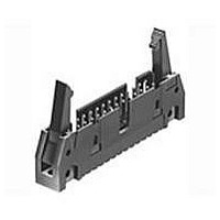
5499206-2
Description
Conn Ejector Header HDR 14 POS 2.54mm Solder ST Thru-Hole
Manufacturer
TE Connectivity
Type
Ejector Headerr
Series
AMP-LATCHr
Datasheet
1.1-499252-1.pdf
(104 pages)
Specifications of 5499206-2
Pitch
2.54 mm
Number Of Rows
2
Number Of Contacts
14
Gender
HDR
Contact Plating
Gold Over Nickel
Termination Method
Solder
Connector Type
Wire To Board
Contact Termination
Through Hole
No. Of Contacts
14
No. Of Rows
2
Pitch Spacing
2.54mm
Rohs Compliant
Yes
Product Type
Headers - Latch / Eject
Number Of Positions / Contacts
14
Mounting Style
Through Hole
Termination Style
Solder
Product Line
AMP-LATCH
Profile
Standard
Pcb Mounting Orientation
Vertical
Pcb Mount Retention
Without
Mating Connector Lock
With
Housing Style
4-Sided
Ejection Latches
With
Post Size (mm [in])
0.64 [.025]
Shrouded
Yes
Latch Type
Long
Mating Connector Lock Type
Latch
Termination Post Length (mm [in])
2.79 [0.110]
Solder Tail Contact Plating
Tin
Header Type
Universal Ejection Pin Headers
Number Of Positions
14
Centerline, Matrix (mm [in])
2.54 x 2.54 [.100 x .100]
Preloaded
Yes
Contact Plating, Mating Area, Material
Gold (30)
Contact Shape
Square
Connector Style
Header - Pin
Mating Alignment Type
Center, Dual Polarizing Bar, Military
Mating Alignment
With
Housing Material
Thermoplastic - GF
Ul Flammability Rating
UL 94V-0
Housing Color
Black
Rohs/elv Compliance
RoHS compliant, ELV compliant
Lead Free Solder Processes
Wave solder capable to 240°C, Wave solder capable to 260°C, Wave solder capable to 265°C
Rohs/elv Compliance History
Always was RoHS compliant
Temperature Rating
Standard
Pcb Thickness, Recommended (mm [in])
1.57 [0.062]
Lead Free Status / Rohs Status
Details


[4.69
.185
Note: All part numbers are RoHS compliant.
Typ.
No. of
± .010
± 0.25
Pos.
10
14
16
20
26
34
40
50
60
]
[4.19]
.165
1.000 [25.40]
1.100 [27.94]
1.300 [33.02]
1.600 [40.64]
2.000 [50.80]
2.300 [58.42]
2.800 [71.12]
3.300 [83.82]
.800 [20.32]
[2.54]
.100
[4.69]
.185
A
A
B
Typ.
Recommended PC Board Hole Layout
+.000
+0.00
-.010
-0.25
Dimensions
]
.015
.010
0.38
0.25
For Manual Insertion
Position No.1
]
Indicator
[0.89
.035
Dia. Typ.
[2.54]
•
.100
1.200 [30.48]
1.600 [40.64]
1.900 [48.26]
2.400 [60.96]
2.900 [73.66]
± .003
± 0.08
.400 [10.16]
.600 [15.24]
.700 [17.78]
.900 [22.86]
[0.64
.025
Typ.
]
[9.86]
± .001
± 0.03
B
.388
[3.31]
Pin 1
Pin 2
.130
]
Typ.
Typ.
[2.54]
.100
[9.14]
.360
[.635
.025
1-5103311-0
1-5103311-2
Typ.
5103311-1
5103311-2
5103311-3
5103311-5
5103311-6
5103311-7
5103311-8
± .001
± 0.03
Plating A
]
Post Plating/Part Nos.
[3.12]
.123
1-5103310-0
[6.09]
.240
5103310-1
5103310-2
5103310-3
5103310-5
5103310-6
5103310-7
5103310-8
Plating B
—
[2.54]
.100
.135
3.42
+.020
+0.51
-.010
-0.25
77
]
Related parts for 5499206-2
Image
Part Number
Description
Manufacturer
Datasheet
Request
R

Part Number:
Description:
Printers THERMAL PRINTER HS-SLEEVE MARKER
Manufacturer:
TE Connectivity


Part Number:
Description:
Manufacturer:
TE Connectivity
Datasheet:


Part Number:
Description:
Manufacturer:
TE Connectivity
Datasheet:

Part Number:
Description:
Manufacturer:
TE Connectivity
Datasheet:

Part Number:
Description:
Manufacturer:
TE Connectivity
Datasheet:


Part Number:
Description:
Manufacturer:
TE Connectivity
Datasheet:

Part Number:
Description:
Manufacturer:
TE Connectivity
Datasheet: