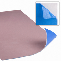
GPVOUS-0.125-00-0816 Bergquist, GPVOUS-0.125-00-0816 Datasheet - Page 16

GPVOUS-0.125-00-0816
Manufacturer Part Number
GPVOUS-0.125-00-0816
Description
THERMAL PAD 8"X16" .125" GP US
Manufacturer
Bergquist
Series
Gap Pad® VOr
Datasheets
1.803129.pdf
(27 pages)
2.GPVOUS-0.020-00-0816.pdf
(1 pages)
3.GPVOUS-0.040-00-0816.pdf
(1 pages)
Specifications of GPVOUS-0.125-00-0816
Usage
Sheet
Shape
Rectangular
Outline
406.40mm x 203.20mm
Thickness
0.125" (3.18mm)
Adhesive
Tacky - One Side
Backing, Carrier
Fiberglass
Color
Pink
Thermal Conductivity
1.0 W/m-K
Packages Cooled
BGA
Operating Temperature Range
-60°C To +200°C
Length
16"
Overall Width
8"
Breakdown Voltage Vbr
6kV
Rohs Compliant
Yes
Lead Free Status / RoHS Status
Lead free / RoHS Compliant
Thermal Resistivity
-
Other names
.125 GP US 8"X16"
BER226
BG426654
BER226
BG426654
14
Selecting A Circuit Layer
t
t
t
Current Carrying Capabilities
The circuit layer is the component-mounting layer in Thermal Clad.
Current carrying capability is a key consideration because this layer
typically serves as a printed circuit, interconnecting the components of
the assembly. The advantage of Thermal Clad is that the circuit trace
interconnecting components can carry higher currents because of its
ability to dissipate heat due to I
Temperature rise comparison graph depicts the significant difference between Bergquist
Dielectric HT and FR-4. Additional comparison charts regarding all Bergquist Dielectrics are
available. Note: No base metal used in calculation.
Current Carrying Capabilities
Heat Spreading Capabilities
Flatness In Relationship To Thickness
10
9
8
7
6
5
4
3
2
1
1" by 0.125" ( 25mm by 3.2mm) trace
or 0.006" (152 µm) FR-4 dielectric
on 0.003" (76 µm) HT dielectric
5
10
2
R loss in the copper circuitry.
15
20
HT
1 oz (35
2 oz (70
1 oz (35
2 oz (70
25
µm)
µm)
µm)
µm)
Temperature rise comparison graph depicts the significant difference between Bergquist
Dielectric HT and FR-4. Additional comparison charts regarding all Bergquist Dielectrics are
available. Note: No base metal used in calculation.
Want a cost effective,
optimized circuit design?
This Thermal Clad White Paper addresses specific design
recommendations including mechanical, circuit, soldermask,
fabrication and test options to help optimize your design.
50
40
30
20
10
0
0
50
1" by 0.125" ( 25mm by 3.2mm) trace
or 0.006" (152 µm) FR-4 dielectric
on 0.003" (76 µm) HT dielectric
100
150
200
HT
1 oz (35
3 oz (105
6 oz (210
10 oz (350
1 oz (35
3 oz (105
6 oz (210
10 oz (350
250
µm)
µm)
µm)
µm)
µm)
µm)
µm)
µm)


