MCP23S09T-E/MG Microchip Technology, MCP23S09T-E/MG Datasheet - Page 21
MCP23S09T-E/MG
Manufacturer Part Number
MCP23S09T-E/MG
Description
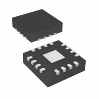
8-bit Input/Output Expander, SPI Interface 16 QFN 3x3x0.9mm T/R
Manufacturer
Microchip Technology
Datasheet
1.MCP23S09-ESO.pdf
(50 pages)
Specifications of MCP23S09T-E/MG
Interface
SPI
Number Of I /o
8
Interrupt Output
Yes
Frequency - Clock
10MHz
Voltage - Supply
1.8 V ~ 5.5 V
Operating Temperature
-40°C ~ 125°C
Mounting Type
Surface Mount
Package / Case
16-QFN
Lead Free Status / RoHS Status
Lead free / RoHS Compliant


1.6.6
The Sequential Operation (SEQOP) controls the
incrementing function of the address pointer. If the
address pointer is disabled, the address pointer does
not automatically increment after each byte is clocked
during a serial transfer. This feature is useful when it is
desired to continuously poll (read) or modify (write) a
register.
The Open-Drain (ODR) control bit enables/disables the
INT pin for open-drain configuration.
REGISTER 1-6:
© 2009 Microchip Technology Inc.
bit 7
Legend:
R = Readable bit
-n = Value at POR
bit 7
bit 6
bit 5
bit 4
bit 3
bit 2
bit 1
bit 0
U-0
-
CONFIGURATION REGISTER
Unimplemented: Reads as 0
Unimplemented: Reads as 0
SEQOP: Sequential Operation mode bit.
1 = Sequential operation disabled, address pointer does not increment
0 = Sequential operation enabled, address pointer increments
Unimplemented: Reads as 0
Unimplemented: Reads as 0
ODR: Configures the INT pin as an open-drain output.
1 = Open-drain output (overrides the INTPOL bit)
0 = Active driver output (INTPOL bit sets the polarity)
INTPOL: Sets the polarity of the INT output pin.
1 = Active-high
0 = Active-low
INTCC: Interrupt Clearing Control
1 = Reading INTCAP register clears the interrupt
0 = Reading GPIO register clears the interrupt
U-0
IOCON – I/O EXPANDER CONFIGURATION REGISTER
-
W = Writable bit
‘1’ = Bit is set
SEQOP
R/W-0
U-0
-
‘0’ = Bit is cleared
U = Unimplemented bit, read as ‘0’
MCP23009/MCP23S09
The Interrupt Polarity (INTPOL) sets the polarity of the
INT pin. This bit is functional only when the ODR bit is
cleared, configuring the INT pin as active push-pull.
The Interrupt Clearing Control (INTCC) configures how
interrupts are cleared. When set (INTCC = 1), the
interrupt is cleared when the INTCAP register is read.
When cleared (INTCC = 0), the interrupt is cleared
when the GPIO register is read.
The interrupt can only be cleared when the interrupt
condition is inactive. Refer to Section 1.7.4 “Clearing
Interrupts” for details.
U-0
-
R/W-0
ODR
x = Bit is unknown
INTPOL
R/W-0
DS22121B-page 21
INTCC
R/W-0
bit 0
Related parts for MCP23S09T-E/MG
Image
Part Number
Description
Manufacturer
Datasheet
Request
R

Part Number:
Description:
8-bit Input/Output Expander, SPI Interface 18 SOIC .300in T/R
Manufacturer:
Microchip Technology
Datasheet:
Part Number:
Description:
IC I/O EXPANDER SPI 8B 18SOIC
Manufacturer:
Microchip Technology
Datasheet:

Part Number:
Description:
IC I/O EXPANDER SPI 8B 18DIP
Manufacturer:
Microchip Technology
Datasheet:

Part Number:
Description:
IC I/O EXPANDER SPI 8B 16QFN
Manufacturer:
Microchip Technology
Datasheet:

Part Number:
Description:
8-Bit I/O Expander
Manufacturer:
Microchip Technology
Datasheet:

Part Number:
Description:
Manufacturer:
Microchip Technology Inc.
Datasheet:
Part Number:
Description:
Manufacturer:
Microchip Technology Inc.
Datasheet:
Part Number:
Description:
Manufacturer:
Microchip Technology Inc.
Datasheet:
Part Number:
Description:
Manufacturer:
Microchip Technology Inc.
Datasheet:
Part Number:
Description:
Manufacturer:
Microchip Technology Inc.
Datasheet:
Part Number:
Description:
Manufacturer:
Microchip Technology Inc.
Datasheet: