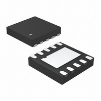
MIC2843YMT TR Micrel Inc, MIC2843YMT TR Datasheet - Page 9

MIC2843YMT TR
Manufacturer Part Number
MIC2843YMT TR
Description
Six Channel Current Sink In 2x2 Thin MLFr
Manufacturer
Micrel Inc
Type
PWM Controlr
Datasheet
1.MIC2843YMT_TR.pdf
(15 pages)
Specifications of MIC2843YMT TR
Constant Current
Yes
Topology
Linear (LDO), PWM
Number Of Outputs
6
Internal Driver
Yes
Type - Primary
Backlight, Flash/Torch
Type - Secondary
White LED
Frequency
500kHz
Voltage - Supply
3 V ~ 5.5 V
Mounting Type
Surface Mount
Package / Case
10-TMLF®
Operating Temperature
-40°C ~ 125°C
Current - Output / Channel
20mA
Internal Switch(s)
Yes
Lead Free Status / RoHS Status
Lead free / RoHS Compliant
Voltage - Output
-
Efficiency
-
Lead Free Status / RoHS Status
Lead free / RoHS Compliant
Other names
576-3507-2
Functional Description
The MIC2843 is a six-channel WLED driver. The WLED
driver is designed to maintain proper current regulation
with LED current accuracy of 1.5% while the typical
matching between the six channels to be 3% at room
temperature. The WLEDs are driven independently from
the input supply and will maintain regulation with a
dropout of 40mV at 20mA. The low dropout of the linear
drivers allows the WLEDs to be driven directly from the
battery voltage and eliminates the need for large and
inefficient charge pumps. The maximum WLED current
for each channel is set via an external resistor. If
dimming is desired the MIC2843 can dim via an Ultra
Fast PWM™ signal.
Block Diagram
As shown in Figure 1, the MIC2843 consists of six
current mirrors set to copy a master current determined
by R
block for enabling and dimming of the WLEDs. The
MIC2843 is controlled by the PWM control block that
receives PWM signals for dimming.
VIN
The input supply (V
drivers and the control circuitry. The V
is 3V to 5.5V. Due to wire inductance a minimum bypass
capacitor of 1µF should be placed close to input (VIN)
pin and the ground (GND) pin. Refer to the Layout
Recommendations section for details on placing the
input capacitor (C1).
END
The END pin is equivalent to the enable pin for the linear
drivers on the MIC2843. It can also be used for dimming
using a PWM signal. See the “PWM Dimming Interface”
in the Application Information section for details.
The first pulse on the END pin must be equal or greater
to 40µs to wake the part up in a known state. This
equates to a 12.5kHz PWM signal at equal or greater
than 50% duty cycle. Higher PWM frequencies may be
used but the first pulse must be equal or greater than
40µs.
Micrel Inc.
November 2010
SET
. The linear drivers have a designated control
IN
) provides power to the linear
IN
operating range
9
R
The R
ground to set the peak current of the linear drivers. The
average LED current can be calculated by Equation 1
below:
D is the duty cycle of the LED current during PWM
dimming. When the device is fully on the duty cycle
equals 100% (D = 1). A plot of I
in Figure 2.
D1-D6
The D1 through D6 pins are the linear driver inputs for
WLED 1 through 6, respectively. Connect the anodes of
the WLEDs to V
through D6. The linear drivers are independent of each
other.
GND
The ground pin is the ground path for the linear drivers.
The current loop for the ground should be as small as
possible. The ground of the input capacitor should be
routed with low impedance traces to the GND pin and
made as short as possible. Refer to the Layout
Recommendations section for more details.
SET
SET
I
LED
pin is used by connecting a R
Figure 2. Peak LED Current vs. R
(mA) = 410 × D / R
IN
and each cathode of the WLEDs to D1
SET
LED
(kΩ)
versus R
M9999-110810-B
SET
SET
SET
MIC2843
resistor to
is shown
Eq. 1


