MIC5314-FFYMT TR Micrel Inc, MIC5314-FFYMT TR Datasheet
MIC5314-FFYMT TR
Specifications of MIC5314-FFYMT TR


Related parts for MIC5314-FFYMT TR


MIC5314-FFYMT TR Summary of contents
Page 1
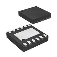
... The MIC5314 can also be put into a zero-off- mode current state, drawing virtually no current when disabled. The MIC5314 is available in fixed output voltages in the 12-pin 2.5mm x 2.5mm Thin MLF Data sheets and support documentation can be found on Micrel’s web site at: www.micrel.com. ...
Page 2
... MIC5314-1.5/1.0YMT MIC5314-FCYMT MIC5314-1.5/1.1YMT MIC5314-F3YMT MIC5314-1.5/1.2YMT MIC5314-F4YMT MIC5314-1.5/1.3YMT MIC5314-F5YMT MIC5314-1.5/1.4YMT MIC5314-F6YMT MIC5314-1.5/1.5YMT MIC5314-FFYMT MIC5314-1.8/1.2YMT MIC5314-G4YMT MIC5314-1.8/1.8YMT MIC5314-GGYMT Notes: 1. Pin 1 identifier = ▲. 2. For other voltage option, contact Micrel Marketing for details ® 3. MLF is a GREEN RoHS compliant package. Lead finish is NiPdAu. Mold compound is Halogen Free. ...
Page 3
... I OUT BYP Min Typ –1.0 OUT2 –2.0 OUT2 0.02 0.02 0.4 0.01 350 550 1.2 0.02 0.2 150 88 = 250µA 0.02 L –1 0.01 MIC5314 BIAS BIAS BIAS ).......................70°C/W = 100µA; OUT Max Units +1 +2.0 %/V 0.3 %/V 0 100 85 mV 200 7 µ ...
Page 4
... Devices are ESD sensitive. Handling precautions recommended. Human body model, 1.5kΩ in series with 100pF. 5. Specification for packaged product only. July 2008 Condition CSET2 POR2 = High (ambient temperature Min Typ 1.4 0.8 1.212 1. – θ . Exceeding the maximum allowable power D(max) J(max MIC5314 Max Units µA 2 1.288 V M9999-070208-A ...
Page 5
... V = 5.5V BIAS 0 10mA OUT 0 1µF OUT1 0 1µF OUT2 0 0 0.5 1 1.5 2 2.5 3 3.5 4 4.5 5 INPUT VOLTAGE (V) 5 MIC5314 Ground Current ( vs. Temperature +1V IN OUT V = 3.6V BIAS V = 1.5V OUT1 1.2V OUT2 C = 1µF OUT ...
Page 6
... Micrel, Inc. Typical Characteristics (continued) Output Noise Spectral Density 1 0.1 0. 1µF OUT C = 10nF BYP 0.001 10 100 1k 10k 100k 1M FREQUENCY (Hz) July 2008 6 MIC5314 M9999-070208-A ...
Page 7
... Micrel, Inc. Functional Characteristics July 2008 7 MIC5314 M9999-070208-A ...
Page 8
... Micrel, Inc. Functional Characteristics (continued) July 2008 8 MIC5314 M9999-070208-A ...
Page 9
... Micrel, Inc. Functional Diagram EN1 VIN1 VBIAS EN2 VIN2 July 2008 THERMAL LIMIT REFERENCE LDO1 CURRENT LIMIT LDO2 GND MIC5314 Block Diagram 9 CBYP QUICK START VOUT1 CSET2 DELAY POR2 POR2 VOUT2 M9999-070208-A MIC5314 ...
Page 10
... The bypass capacitor can be increased, further reducing noise and improving PSRR. Turn-on time increases capacitance. A unique, quick-start circuit allows the MIC5314 to drive a large capacitor on the bypass pin without significantly slowing turn-on time. No-Load Stability Unlike many other voltage regulators, the MIC5314 will remain stable and in regulation with no load ...
Page 11
... GND conditions for the regulator circuit. The maximum power dissipation must not be exceeded for proper operation. For example, when operating the MIC5314-FCYMT at an input voltage of 1.8V and 300mA, loads at each output with a minimum footprint layout, the maximum ambient operating temperature T ambient ...
Page 12
... Micrel, Inc. MIC5314 Typical Application Circuit VIN J1 VIN R1 100k J3 VBIAS J4 EN1 J5 EN2 C1 1µF J2 GND Bill of Materials Item Part Number C1, C2, C5, C6 C1608X5R1A105K C3 VJ0603Y104KXACW1BC C4 VJ0603Y103KXACW1BC R1 CRCW0603100KFKEA U1 MIC5314-xxYMT Notes: 1. TDK: www.tdk.com 2. Vishay: www.vishay.com 3. Micrel, Inc.: www.micrel.com July 2008 U1 MIC5314-xxYMT 1 VIN1 VOUT1 2 VIN2 ...
Page 13
... Micrel, Inc. PCB Layout Recommendations July 2008 Top Layer Bottom Layer 13 MIC5314 M9999-070208-A ...
Page 14
... Purchaser’s use or sale of Micrel Products for use in life support appliances, devices or systems is a Purchaser’s own risk and Purchaser agrees to fully July 2008 12-Pin 2.5mm × 2.5mm Thin MLF indemnify Micrel for any damages resulting from such use or sale. © 2008 Micrel, Incorporated. 14 ® (MT) M9999-070208-A MIC5314 ...