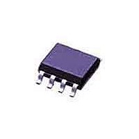
MTD6501D-HC1 Microchip Technology, MTD6501D-HC1 Datasheet - Page 8

MTD6501D-HC1
Manufacturer Part Number
MTD6501D-HC1
Description
12V, 3-Phase Full-Wave Drivers 10 MSOP 3x3mm TUBE
Manufacturer
Microchip Technology
Type
3-Phase Brushless DC Sinusoidal Sensorless Fan Motor Driverr
Datasheet
1.MTD6501D-HC1.pdf
(16 pages)
Specifications of MTD6501D-HC1
Product
Fan / Motor Controllers / Drivers
Operating Supply Voltage
2 V to 14 V
Supply Current
5 mA, 10 mA
Mounting Style
SMD/SMT
Package / Case
SOIC-8
Operating Temperature
- 10 C to + 85 C
Lead Free Status / RoHS Status
Lead free / RoHS Compliant
Lead Free Status / RoHS Status
Lead free / RoHS Compliant
Available stocks
Company
Part Number
Manufacturer
Quantity
Price
Company:
Part Number:
MTD6501D-HC1
Manufacturer:
AVAGO
Quantity:
1 000
MTD6501C/MTD6501D
3.0
The MTD6501C/MTD6501D devices generate a full-
wave signal to drive a 3-phase sensorless BLDC motor.
High efficiency and low-power consumption are
achieved due to DMOS transistors and synchronous
rectification drive type. The current carrying order of the
outputs is as follows: OUT1 -> OUT2 -> OUT3.
3.1
The rotational speed of the motor can be controlled
either through the PWM digital input signal or by acting
directly on the power supply (V
nal is “High” (or left open) the motor rotates at full
speed. When the PWM signal is “Low” the motor is
stopped (and the IC outputs are set to high-imped-
ance). By changing the PWM duty cycle, the speed can
be adjusted. Notice that the PWM frequency has no
special meaning for the motor speed and is asynchro-
nous with the activation of the output transistors. Thus
the user has maximum freedom to choose the PWM
system frequency within a wide range (from 20 Hz to
100 kHz), while the output transistor activation always
occurs at a fixed rate (20 kHz, typ.), which is outside of
the range of audible frequencies.
3.2
The Frequency Generator output (FG) is a “Hall-sensor
equivalent” digital output, giving information to an
external controller about the speed and phase of the
motor. The FG pin is an open collector output, connect-
ing to a logical voltage level through an external pull-up
resistor. When a lock (or out-of-sync) situation is
detected by the driver, this output is set to high-imped-
ance until the motor is restarted. Leave the pin open
when not used.
3.3
If the motor is stopped (blocked) or if it loses synchro-
nization with the driver, a lock-up protection circuit
detects this situation and disables the driver (by setting
its outputs to high-impedance) in order to prevent the
motor coil from burnout. After a “waiting time” (T
the lock-up protection is released and normal operation
resumes for a given time (T
still blocked, a new period of waiting time is started.
T
external capacitor is needed.
DS22263A-page 8
WAIT
and T
FUNCTIONAL DESCRIPTION
Speed Control
Frequency Generator Function
Lockup Protection and Automatic
Restart
RUN
timings are fixed internally, so that no
RUN
CC
). In case the motor is
). When the PWM sig-
WAIT
),
3.4
The motor peak current is limited by the driver to a fixed
value (defined internally), thus limiting the maximum
power dissipation in the coils. The detection of a short-
circuit situation immediately sets the driver outputs to
high-impedance, in order to avoid permanent damage
to the IC.
3.5
The MTD6501C/MTD6501D have a thermal protection
function which detects when the die temperature
exceeds T
reached, the circuit enters the thermal shutdown mode
and the outputs OUT1, OUT2 and OUT3 are disabled
(high-impedance), avoiding IC destruction and allowing
the circuit to cool down. Once the junction temperature
(T
resumes (thermal detection circuit has 25°C hysteresis
function).
FIGURE 3-1:
Hysteresis
3.6
V
supply internal logical blocks. The V
connect an external decoupling capacitor (1µF or
higher). Notice that this pin is for IC internal use and is
not designed to supply DC current to external blocks.
DD
J
) has dropped below 145°C, the normal operation
Normal operation
voltage is generated internally and is used to
Overcurrent Protection and Short
Circuit Detection
Thermal Shutdown
Internal Voltage Regulator
J
= 170°C. When this temperature is
145°
Thermal Protection
2010 Microchip Technology Inc.
170°
Thermal shut -down
DD
pin is used to
T
J


