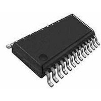
PIC16LF1903-E/SS Microchip Technology, PIC16LF1903-E/SS Datasheet - Page 236

PIC16LF1903-E/SS
Manufacturer Part Number
PIC16LF1903-E/SS
Description
7KB Flash, 256B RAM, LCD, 11x10b ADC, NanoWatt XLP 28 SSOP .209in TUBE
Manufacturer
Microchip Technology
Series
PIC® XLP™ 16Fr
Datasheet
1.PIC16LF1902-EMV.pdf
(240 pages)
Specifications of PIC16LF1903-E/SS
Processor Series
PIC16LF190x
Core
PIC
Data Bus Width
8 bit
Program Memory Type
Flash
Program Memory Size
4 KB
Data Ram Size
256 B
Maximum Clock Frequency
20 MHz
Number Of Programmable I/os
25
Number Of Timers
2
Operating Supply Voltage
1.8 V to 3.6 V
Maximum Operating Temperature
+ 125 C
Mounting Style
SMD/SMT
Package / Case
SSOP-28
Core Processor
PIC
Core Size
8-Bit
Speed
20MHz
Connectivity
-
Peripherals
Brown-out Detect/Reset, LCD, POR, PWM, WDT
Number Of I /o
25
Eeprom Size
-
Ram Size
256 x 8
Voltage - Supply (vcc/vdd)
1.8 V ~ 3.6 V
Data Converters
A/D 11x10b
Oscillator Type
Internal
Operating Temperature
-40°C ~ 125°C
Lead Free Status / Rohs Status
Details
PIC16LF1902/3
Stack Overflow/Underflow................................................... 46
STATUS Register................................................................ 19
SUBWFB........................................................................... 193
T
T1CON Register.......................................................... 25, 139
T1GCON Register............................................................. 140
Temperature Indicator Module .......................................... 111
Thermal Considerations .................................................... 202
Timer0 ............................................................................... 127
Timer1 ............................................................................... 131
Timers
Timing Diagrams
Timing Parameter Symbology........................................... 203
TMR0 Register .................................................................... 25
TMR1H Register ................................................................. 25
TMR1L Register .................................................................. 25
TRIS .................................................................................. 194
DS41455B-page 236
Accessing.................................................................... 30
Reset........................................................................... 32
Associated Registers ................................................ 129
Operation .................................................................. 127
Specifications ............................................................ 209
Associated registers.................................................. 141
Asynchronous Counter Mode ................................... 133
Clock Source Selection ............................................. 132
Interrupt..................................................................... 135
Operation .................................................................. 132
Operation During Sleep ............................................ 135
Oscillator ................................................................... 133
Prescaler ................................................................... 133
Specifications ............................................................ 209
Timer1 Gate
TMR1H Register ....................................................... 131
TMR1L Register ........................................................ 131
Timer1
A/D Conversion ......................................................... 211
A/D Conversion (Sleep Mode) .................................. 211
Brown-out Reset (BOR) ............................................ 206
Brown-out Reset Situations ........................................ 45
CLKOUT and I/O....................................................... 205
INT Pin Interrupt.......................................................... 64
Internal Oscillator Switch Timing................................. 56
LCD Interrupt Timing in Quarter-Duty Cycle Drive.... 172
LCD Sleep Entry/Exit when SLPEN = 1 or CS = 00 . 174
Reset Start-up Sequence............................................ 47
Reset, WDT, OST and Power-up Timer ................... 206
SPI Slave Mode (CKE = 0) ....................................... 212
Timer0 and Timer1 External Clock ........................... 208
Timer1 Incrementing Edge........................................ 135
Type-A in 1/2 MUX, 1/2 Bias Drive ........................... 161
Type-A in 1/2 MUX, 1/3 Bias Drive ........................... 163
Type-A in 1/3 MUX, 1/2 Bias Drive ........................... 165
Type-A in 1/3 MUX, 1/3 Bias Drive ........................... 167
Type-A in 1/4 MUX, 1/3 Bias Drive ........................... 169
Type-A/Type-B in Static Drive................................... 160
Type-B in 1/2 MUX, 1/2 Bias Drive ........................... 162
Type-B in 1/2 MUX, 1/3 Bias Drive ........................... 164
Type-B in 1/3 MUX, 1/2 Bias Drive ........................... 166
Type-B in 1/3 MUX, 1/3 Bias Drive ........................... 168
Type-B in 1/4 MUX, 1/3 Bias Drive ........................... 170
Wake-up from Interrupt ............................................... 74
Reading and Writing ......................................... 133
Selecting Source............................................... 133
T1CON.............................................................. 139
T1GCON ........................................................... 140
Preliminary
TRISA Register............................................................. 25, 95
TRISB ................................................................................. 97
TRISB Register............................................................. 25, 98
TRISC ............................................................................... 100
TRISC Register........................................................... 25, 101
TRISE ............................................................................... 103
TRISE Register........................................................... 25, 103
U
USART
V
V
W
Wake-up Using Interrupts ................................................... 74
Watchdog Timer (WDT)...................................................... 46
WDTCON Register ............................................................. 77
WPUB Register................................................................... 99
Write Protection .................................................................. 40
WWW Address ................................................................. 233
WWW, On-Line Support ....................................................... 8
REF
Synchronous Master Mode
Modes ......................................................................... 76
Specifications ........................................................... 208
. S
EE
Requirements, Synchronous Transmission...... 212
ADC Reference Voltage
2011 Microchip Technology Inc.


