SY56017RMG Micrel Inc, SY56017RMG Datasheet - Page 4
SY56017RMG
Manufacturer Part Number
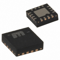
SY56017RMG
Description
1.2/1.8V Low Voltage CML 2:1 MUX W/ EQ
Manufacturer
Micrel Inc
Series
Precision Edge®r
Type
Multiplexerr
Datasheet
1.SY56017RMG.pdf
(12 pages)
Specifications of SY56017RMG
Number Of Circuits
1
Ratio - Input:output
2:1
Differential - Input:output
Yes/Yes
Input
CML, LVDS, LVPECL
Output
CML
Frequency - Max
4.5GHz
Voltage - Supply
2.375 V ~ 2.625 V
Operating Temperature
-40°C ~ 85°C
Mounting Type
Surface Mount
Package / Case
16-MLF®, QFN
Frequency-max
4.5GHz
Lead Free Status / RoHS Status
Lead free / RoHS Compliant
Other names
576-3289-5


Micrel, Inc.
Absolute Maximum Ratings
Supply Voltage (V
Supply Voltage (V
V
V
Input Voltage (V
CML Output Voltage (V
Current (V
Input Current
Maximum operating Junction Temperature .......... 125°C
Lead Temperature (soldering, 20sec.) .................. 260°C
Storage Temperature (T
DC Electrical Characteristics
T
Notes:
1. Permanent device damage may occur if absolute maximum ratings are exceeded. This is a stress rating only and functional operation is not
2. The data sheet limits are not guaranteed if the device is operated beyond the operating ratings.
3. Package thermal resistance assumes exposed pad is soldered (or equivalent) to the device's most negative potential on the PCB. ψ
4. The circuit is designed to meet the DC specifications shown in the above table after thermal equilibrium has been established.
5. V
Symbol
V
I
I
R
R
V
V
V
V
V
July 2008
A
CC
CCO
CC
CCO
CC
IH
IL
IN
DIFF_IN
T_IN
IN
DIFF_IN
= –40°C to +85°C, unless otherwise stated.
implied at conditions other than those detailed in the operational sections of this data sheet. Exposure to absolute maximum ratings conditions for
extended periods may affect device reliability.
values are determined for a 4-layer board in still-air number, unless otherwise stated.
- V
Source or sink on VT pin ............................. ±100mA
Source or sink Current on (IN, /IN) ................ ±50mA
IN
- V
(max) is specified when V
CCO
CC
T
............................................................... <1.8V
............................................................... <0.5V
)
Parameter
Power Supply Voltage Range
Power Supply Current
Power Supply Current
Input Resistance
(IN-to-V
Differential Input Resistance
(IN-to-/IN)
Input HIGH Voltage
(IN, /IN)
Input LOW Voltage
(IN, /IN)
Input Voltage Swing
(IN, /IN)
Differential Input Voltage Swing
(|IN - /IN|)
Voltage from Input to V
IN
) ....................................... –0.5V to V
CC
CCO
T
) ............................... –0.5V to +3.0V
, /IN-to-V
) ............................. –0.5V to +3.0V
OUT
s
) .................... –65°C to +150°C
T
) ......................... 0.6V to 3.0V
is floating.
T
)
T
(1)
(4)
Condition
V
V
V
V
Max. V
No Load. V
IN, /IN
IN, /IN
1.22V = 1.7-0.475
see Figure 3a, Note 5, applied to
input of transmission line.
see Figure 3b, Note 5, applied to
input of transmission line.
CC
CCO
CCO
CCO
CC
CC
CCO
Operating Ratings
Supply Voltage (V
2.625V
Ambient Temperature (T
Package Thermal Resistance
4
QFN
Still-air (θ
Junction-to-board (ψ
(V
JA
CCO
CC
hbwhelp@micrel.com
) ............................................ 75°C/W
2.375
2.375
1.14
1.42
1.22
Min
1.7
0.2
0.4
45
90
) .......................... 2.375V to 2.625V
)……………..……1.14V to
A
(2)
) ................... –40°C to +85°C
JB
Typ
100
(3)
2.5
1.2
1.8
2.5
) ......................... 33°C/W
55
16
50
V
or (408) 955-1690
M9999-070308-A
2.625
2.625
Max
1.26
IH
1.28
110
V
1.9
2.0
1.0
80
21
55
–0.2
CC
SY56017R
JB
and θ
Units
mA
mA
Ω
Ω
V
V
V
V
V
V
V
V
V
JA
Related parts for SY56017RMG
Image
Part Number
Description
Manufacturer
Datasheet
Request
R

Part Number:
Description:
Manufacturer:
Micrel Inc
Datasheet:
Part Number:
Description:
Manufacturer:
Micrel Inc
Datasheet:
Part Number:
Description:
Manufacturer:
Micrel Inc
Datasheet:
Part Number:
Description:
Manufacturer:
Micrel Inc
Datasheet:
Part Number:
Description:
Manufacturer:
Micrel Inc
Datasheet:
Part Number:
Description:
Manufacturer:
Micrel Inc
Datasheet:
Part Number:
Description:
Manufacturer:
Micrel Inc
Datasheet:
Part Number:
Description:
Manufacturer:
Micrel Inc
Datasheet:
Part Number:
Description:
Manufacturer:
Micrel Inc
Datasheet:
Part Number:
Description:
Manufacturer:
Micrel Inc
Datasheet:
Part Number:
Description:
Manufacturer:
Micrel Inc
Datasheet:
Part Number:
Description:
Manufacturer:
Micrel Inc
Datasheet:
Part Number:
Description:
Manufacturer:
Micrel Inc
Datasheet:
Part Number:
Description:
Manufacturer:
Micrel Inc
Datasheet: