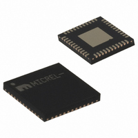
SY56040ARMY TR Micrel Inc, SY56040ARMY TR Datasheet - Page 8

SY56040ARMY TR
Manufacturer Part Number
SY56040ARMY TR
Description
LV CML 4x4 Crosspoint W/o EQ
Manufacturer
Micrel Inc
Datasheet
1.SY56040ARMY.pdf
(14 pages)
Specifications of SY56040ARMY TR
Function
Crosspoint Switch
Circuit
1 x 4:4
Voltage Supply Source
Single Supply
Voltage - Supply, Single/dual (±)
2.375 V ~ 2.625 V, 1.14 V ~ 1.9 V
Operating Temperature
-40°C ~ 85°C
Mounting Type
Surface Mount
Package / Case
44-MLF®, QFN
Lead Free Status / RoHS Status
Lead free / RoHS Compliant
Other names
576-3311-2
Switch Configuration
As shown in the Simplified Control Circuit below,
Figure 1a, each output channel consists of two sets of
latches. The first set of latches stores the SIN
information for each SOUT selected. The second set
of latches transfers this stored information to the
output MUX circuitry. These latches are transparent
when EN is high and latched when EN is low.
Two
programming. LOAD is ANDed with the SOUT pins to
route the SIN data to the appropriate first set of
latches.
information in the first set of latches to the second set
of latches, which is connected to the output MUX
circuitry.
There are two ways to program this device. The first
is a Dual Control Mode, as shown in Figure 1b. First,
all the input-output (SIN-SOUT) information is loaded.
Second, this information is transferred to the output
control circuitry. Each LOAD pulse loads the input
information (SIN) to be assigned to the output
(SOUT). In maximum, four LOAD pulses are applied,
one LOAD pulse for each output. Note that LOAD
pulses are necessary only for undefined and/or
modified input-output combinations.
input-output information is loaded, the CONFIG is
pulsed to transfer and latch this information to the
output control circuitry.
The second programming method is the Single
Control Mode, shown in Figure 1c, in which LOAD and
CONFIG are tied together.
receives the appropriate input information in a one-
shot control pulse.
programmed, the other outputs remain unaffected
until its turn occurs.
September 2008
pins,
CONFIG
LOAD
subsequently
and
When one output is being
CONFIG,
Each individual output
transfers
After all the
Figure 1a. Simplified Control Circuit
control
the
the
8
Interface Applications
For Input Interface Applications, see Figures 4a
through 4f. For CML Output Termination, see Figures
5a through Figure 5d.
CML Output Termination with VCCO 1.2V
For VCCO of 1.2V, Figure 5a, terminate the output
with 50Ω to1.2V, DC-coupled, not 100Ω differentially
across the outputs.
If AC-coupling is used, Figure 5d, terminate into 50Ω-
to-1.2V before the coupling capacitor and then
connect to a high value resistor to a reference
voltage.
Do not AC-couple with internally terminated receiver,
such as 50Ω ANY-IN input. AC-coupling will offset the
output voltage by 200mV and this offset voltage will
be too low for proper driver operation. Any unused
output pair needs to be terminated when VCCO is
1.2V, do not leave floating.
CML Output Termination with VCCO 1.8V, 2.5V
For VCCO of 1.8V and 2.5V, refer to Figure 5a and
Figure 5b, terminate with either 50Ω to VCCO or
100Ω differentially across the outputs. See Figure 5c
for AC-coupling.
Input AC-Coupling
The SY56040AR input can accept AC-coupling from
any driver. Bypass VT with a 0.1µF low ESR capacitor
to VCC as shown in Figures 4c and 4d. VT has an
internal high impedance resistor divider as shown in
Figure 2a, to provide a bias voltage for AC-coupling.
hbwhelp@micrel.com
or (408) 955-1690
M9999-093008-A


