V23105-A5476-A201 Tyco Electronics, V23105-A5476-A201 Datasheet
V23105-A5476-A201
Specifications of V23105-A5476-A201


Related parts for V23105-A5476-A201


V23105-A5476-A201 Summary of contents
Page 1
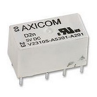
... Signal Relays D2n Relay V23105 Standard DIL relay n Dimensions 20x10x11mm (.795x.394x.433”) n Switching and continous current form C contacts (2 CO, 2 changeover contacts) n Immersion cleanable n Four different coil sensitivities, 150mW, 200mW, 400mW, >500mW n Surge voltage resistance meets FCC Part 68 requirement: 1.5kV n (10/700μs) between coil and contacts ...
Page 2
... A 2.2 max. U rel. min. 2 1.8 1.6 AXICOM 1.4 Insulation Data Telecom-, Signal and RF Relays 1.2 Initial dielectric strength 108-98007 Rev A U nominal coil voltage D2n V23105 Relay 1 nom. 0.8 U op. min. 0.6 U rel. min. 0.4 Initial surge withstand voltage 0 100 110 120 ...
Page 3
... Signal Relays D2n Relay V23105 Dimensions 20.2+0.05/-0.02 0.5 Product code structure Type V23105-A5 Coil Coil code: please refer to coil versions table Coil power 0xxx 150 mW 4xxx 3xxx 300 mW 5xxx Contacts A201 2 form C, 2 CO, AgNi+Au contacts Product Code Version V23105A5001A201 AgNi+Au ...
Page 4
... Rev. 0211 Datasheets and product specification ac- cording to IEC 61810-1 and to be used only www.te.com together with the ‘Definitions’ section. © 2011 Tyco Electronics Ltd. Coil Data Magnetic system Coil voltage range Operative range, IEC 61810 Max. coil temperature 1 form C (CO) ...