1-66099-5 TE Connectivity, 1-66099-5 Datasheet - Page 5
1-66099-5
Manufacturer Part Number
1-66099-5
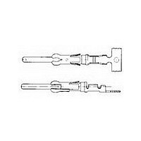
Description
Contact PIN Crimp ST Cable Mount Loose Piece
Manufacturer
TE Connectivity
Type
Contactr
Series
Type III+r
Specifications of 1-66099-5
Connector Type
Connector Circular
Contact Type
Power
Contact Material
Brass
Contact Plating
Tin Over Nickel
Gender
PIN
Termination Method
Crimp
Contact Gender
PIN
Number Of Contacts
1POS
Mounting Style
Cable
Shell Plating
Not Required
Body Orientation
Straight
Strain Relief
Not Required
Product Length (mm)
27.12mm
Product Depth (mm)
3.68mm
Current Rating
13A
Contact Size
16
Rohs Compliant
Yes
Insulation Support
Yes
Termination Method To Wire/cable
Crimp
Wire/cable Type
Discrete Wire
Grade
Commercial
High Current
No
Termination End Plating
Bright Tin
Pin Diameter (mm [in])
1.57 [0.062]
Wire Range (mm [awg])
0.80-1.40² [18-16]
Spring Material
Stainless Steel
Used With
G Series Connectors, M Series Connectors, CPC Connectors
Contact Classification
Signal
Contact Plating, Mating Area, Material
Bright Tin
Contact Base Material
Brass
Rohs/elv Compliance
RoHS compliant, ELV compliant
Lead Free Solder Processes
Not relevant for lead free process
Rohs/elv Compliance History
Always was RoHS compliant
Accepts Wire Insulation Diameter, Range (mm [in])
2.03 – 2.54 [0.080 – 0.100]
Applies To
Wire/Cable
Test Current (a)
13.0
Packaging Method
Loose Piece
Packaging Quantity
1,000 Box/Carton
Lead Free Status / RoHS Status
Compliant
For Use With
G Series Connectors, CPC Connectors, M Series Connectors
Lead Free Status / Rohs Status
RoHS Compliant part
Available stocks
Company
Part Number
Manufacturer
Quantity
Price
Company:

Part Number:
1-66099-5
Manufacturer:
AMP
Quantity:
48 859
Company:
Part Number:
1-66099-5
Manufacturer:
TE
Quantity:
35 000


Catalog 82045
Revised 06-08
www.tycoelectronics.com
Dimensions are in millimeters
and inches unless otherwise
specified. Values in brackets are
equivalent U.S. Customary Units.
AMP Metrimate
Pin and Socket Connectors
Performance Characteristics
•
Practical Values
The current-rating method
gives designers practical val-
ues applicable to their appli-
cations. While the specified
current levels for a contact
may be lower than for other
testing methods, they are
more realistic and simplify
the system design process.
"Spec-manship" is replaced
by a realistic assessment of
the current-carrying capacity
of a contact under varying
conditions of temperature,
connector loading, and wire
size.
contact. The curve is usu-
ally flat up to 75°C ambient
and then drops off. Up to
75°C, the 30°C T-rise limits
the amount of current, and
above 75°C the current
must be reduced to keep
the combination of ambi-
ent temperature and T-rise
from exceeding the maxi-
mum operating tempera-
ture of 105°C.
Next are rating factors, a
table of multipliers to
account for connector
loading and for smaller
wire sizes. The designer
first determines the base
current for the ambient
conditions of the applica-
tion, then multiplies this
base current by the rating
factors to find the current
level for the application's
loading factor and wire
size.
Dimensions are shown for
reference purposes only.
Specifications subject
to change.
Graph shows the relationship between base current, ambient tem-
perature, and contact T-rise.
Rating factors allow the base current to be adjusted for various con-
nector loading and wire sizes.
An Example:
To demonstrate the method of specifying current, consider the
following application conditions, an ambient temperature of
65°C, a 50% loading of contacts in the housing, and 20 AWG
[0.6 mm2] wire.
•
•
•
•
•
0
From Figure 1, the base current rating is 14 ampere with 18
AWG [0.8 mm2] wire.
Figure 2, the rating factor for 50% loading and 20 AWG [0.6
mm2] wire is 0.68.
The specific rating for this application is the product of the
base rating and the rating factor:
Each of the contacts can carry 9.5 ampere.
However, if the ambient temperature is 80
T-rise becomes 25°C. The base current must be lowered to
12.8 ampere so that the 105
ture is not exceeded. The current rating then becomes:
Single
100%
12.8 x 0.68 = 8.7 ampere.
30%
50%
70%
14 x 0.68 = 9.5 ampere
10
USA: 1-800-522-6752
Canada: 1-905-470-4425
Mexico: 01-800-733-8926
C. America: 52-55-5-729-0425
(Continued)
20
NOTE: All part numbers
are RoHS Compliant
.97
.83
.65
.55
18
1
30
Ambient Temperature (°C)
40
.83
.80
.68
.53
.45
20
50
°
Figure 2
Figure 1
C maximum operating tempera-
AWG
.69
.66
.57
.45
.38
22
60
South America: 55-11-3611-1514
Hong Kong: 852-2735-1628
Japan: 81-44-844-8013
UK: 44-141-810-8967
70
.59
.57
.48
.38
.32
24
°C the allowable
80
Single Contact
.50
.49
.42
.33
.28
26
90
[0.8 mm
18 AWG
100
2
]
15
10
5
0
5
Related parts for 1-66099-5
Image
Part Number
Description
Manufacturer
Datasheet
Request
R

Part Number:
Description:
RELAY SSR SCR OUT 125A 480VAC
Manufacturer:
TE Connectivity
Datasheet:

Part Number:
Description:
CONN PIN .062 14-18AWG AU CRIMP
Manufacturer:
Tyco Electronics
Datasheet:

Part Number:
Description:
CONN SOCKET 22-26AWG GOLD CRIMP
Manufacturer:
Tyco Electronics
Datasheet:

Part Number:
Description:
CONN SKT .062 14-18AWG TIN CRIMP
Manufacturer:
Tyco Electronics
Datasheet:

Part Number:
Description:
CONN PIN 18-14AWG TIN CRIMP
Manufacturer:
Tyco Electronics
Datasheet:

Part Number:
Description:
Manufacturer:
TE Connectivity
Datasheet:

Part Number:
Description:
Manufacturer:
TE Connectivity
Datasheet:

Part Number:
Description:
Manufacturer:
TE Connectivity
Datasheet:

Part Number:
Description:
Manufacturer:
TE Connectivity
Datasheet:

Part Number:
Description:
Manufacturer:
TE Connectivity
Datasheet:

Part Number:
Description:
PLCC SOCKET, 68POS, THROUGH HOLE
Manufacturer:
TE Connectivity
Datasheet:

Part Number:
Description:
DIP SOCKET, 20POS, THROUGH HOLE
Manufacturer:
TE Connectivity
Datasheet:

Part Number:
Description:
Conn Unshrouded Header HDR 16 POS 2.54mm Solder ST Thru-Hole
Manufacturer:
TE Connectivity
Datasheet:

Part Number:
Description:
FFC/FPC CONNECTOR, RECEPTACLE 16POS 1ROW
Manufacturer:
TE Connectivity
Datasheet:

Part Number:
Description:
Connector Accessories CPC Clamp Thermoplastic Black Individual
Manufacturer:
TE Connectivity
Datasheet: