ST1-DC12V PANASONIC EW, ST1-DC12V Datasheet - Page 5
ST1-DC12V
Manufacturer Part Number
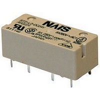
ST1-DC12V
Description
POWER RELAY SPST-NO/NC 12VDC 8A PC BOARD
Manufacturer
PANASONIC EW
Datasheet
1.ST1-DC12V.pdf
(5 pages)
Specifications of ST1-DC12V
Relay Type
PCB
Coil Voltage Vdc Nom
12V
Contact Current Max
8A
Contact Voltage Ac Nom
380V
Contact Voltage Dc Nom
250V
Coil Resistance
600ohm
Contact Configuration
SPST
Lead Free Status / RoHS Status
Lead free / RoHS Compliant
Available stocks
Company
Part Number
Manufacturer
Quantity
Price
Company:

Part Number:
ST1-DC12V
Manufacturer:
tyco
Quantity:
5 400
Company:
Part Number:
ST1-DC12V-F
Manufacturer:
ST
Quantity:
13 000
Part Number:
ST1-DC12V-F
Manufacturer:
PANASON
Quantity:
20 000


ST relay socket
ST-PS
PC board terminal socket
ST
ST-SS
Solder terminal socket
FEATURES
1. Possible to fit or remove the
2. Easy design of PC board pattern
3. Complies with Japan Electrical
4. High breakdown voltage.
PRECAUTIONS FOR USE (SOCKET)
1. PC board mounting method
PC board pattern
The terminal configuration is symmetrical
on the left and right, so an arrow mark
is stamped on the socket to prevent mis-
insertion. We recommend printing the
same arrow mark
mounting side (side opposite from
pattern) of the PC board. In this case, the
terminal configuration becomes the
terminal nos. noted near the drilling
holes.
5
Contact
terminal
interval
Coil
terminal
interval
chassis with one touch (t = 0.6 mm
to 2.2 mm
(2.54 mm x 4 pitch DIL terminal array)
Appliance and Material Safety Law.
(UL and VDE certification)
8-.060 dia.
8-1.5 dia.
8
1
.024 inch to .087
7
2
on the component
6
3
5
4
inch)
2.54
.100
2.54
.100
DIMENSIONS
ST-PS
SPECIFICATIONS
2. Chassis cutout
Chassis cutting dimensions
If the chassis hole is punched with a
press, set so the release R on the front
side (A side).
The range for chassis thickness is 0.6 to
2.2 mm
Breakdown voltage (Initial)
Insulation resistance (Initial)
Heat resistance
Max. continuous current
Relay insertion life
A side
8
1
7.62
.300
7
2
10.16
1.244
1.394
.400
31.6
35.4
.024 to .087
ACCESSORIES
Item
6
3
7.62
.300
1.280±.004
1.05
.041
32.5±0.1
5
4
Press
16.6
.654
.012
.169
0.3
4.3
inch.
0.27
.011
(Unit: mm inch)
Chassis t = 0.6 to 2.2
.591±.008
15.0±0.2
Between contact and coil: 4,000 Vrms for 1 min. (Detection current: 10 mA)
Between contact and terminal: 2,000 Vrms for 1 min.
Min. 1,000 M between terminals (500V DC)
150C
10 A
15 times
10.16
.400
14.6
.575
Claw for chassis
fastening
.024 to .087
302F
.158
.217
5.5
4
for 1 hr
16.4
.646
ST-SS
3. Relay mounting and removal
(1) Align the directions of the relay and
socket.
(2) Insert the relay all the way in, so it is
securely in place.
(3) Press the part indicated by A in the B
direction, and fasten by placing the hook
on the relay.
(4) When removing the relay, completely
release the hooks on both sides and pull
the relay out.
cross-section
7.62
.300
8
1
ST RELAYS
Relay case
Specifications
7
2
SOCKET
10.16
1.244
1.394
.400
31.6
35.4
(Before fastening)
.090
6
3
7.62
.300
2.3
ds_61A09_en_st: 250210D
5
4
Relay
.012
.209
16.6
.654
0.3
5.3
0.27
.011
A
(Fastening complete)
Hinge
mechanism
10.16
.400
14.6
.575
.158
.217
5.5
4
VDE
16.4
.646
Related parts for ST1-DC12V
Image
Part Number
Description
Manufacturer
Datasheet
Request
R


Part Number:
Description:
RELAY, SPNO/SPNC, 12V
Manufacturer:
PANASONIC EW
Datasheet:
Part Number:
Description:
ST Relay (2 Coil Latch, AgSnO2)
Manufacturer:
PANASONIC EW
Datasheet:

Part Number:
Description:
SWITCH
Manufacturer:
APEM Components
Datasheet:
Part Number:
Description:
ST Relay (Cd-Free)
Manufacturer:
PANASONIC EW
Datasheet:

Part Number:
Description:
SIGNAL RELAY, DPDT, 5VDC, 2A, PC BOARD
Manufacturer:
PANASONIC EW
Datasheet:


Part Number:
Description:
PHOTOMOS RELAY, 60VDC, 400mA
Manufacturer:
PANASONIC EW
Datasheet:

Part Number:
Description:
PHOTOMOS RELAY, 400V, 150mA
Manufacturer:
PANASONIC EW
Datasheet: