FN660-20-10 Schaffner EMC Inc, FN660-20-10 Datasheet - Page 7
FN660-20-10
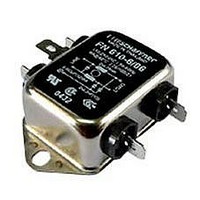
Manufacturer Part Number
FN660-20-10
Description
FILTER 2-STAGE GENERAL 20A
Manufacturer
Schaffner EMC Inc
Series
FN 660r
Specifications of FN660-20-10
Filter Type
Power Line
Voltage - Rated
250V
Current
20A
Inductance
480µH
Mounting Type
Chassis Mount
Termination Style
Stud Lug
Current Rating
20A
Voltage Rating
250V
Leakage Current Max
190µA
Capacitance
0.15µF
Inductance Min
480µH
Termination Type
Screw
Lead Free Status / RoHS Status
Lead free / RoHS Compliant
Lead Free Status / RoHS Status
Lead free / RoHS Compliant, Lead free / RoHS Compliant
Other names
282-352
817-1225
FN 660 -20 /10
817-1225
FN 660 -20 /10
Available stocks
Company
Part Number
Manufacturer
Quantity
Price
Company:

Part Number:
FN660-20-10
Manufacturer:
Schaffner EMC Inc
Quantity:
135


The inductors L1 and 2 are usually wound
- in a current compensated fashion - on a
toroidal core. This winding method allows
flux due to differential mode currents and
mains currents to cancel each other, while
common mode currents will be added
together. This gives a large inductance to
common mode currents and ensures that
the inductor will not be saturated by the
large magnetic flux produced by the mains
current.
The capacitors placed between the
phases, known as ‘X’ class capacitors
must offer a high pulse voltage rating and
are used to attenuate differential mode
interference. The capacitors between the
phase lines and earth, known as ‘Y’ class
capacitors must have a more stringent
rating and are used to attenuate common
mode interference. The value of the Y
capacitor is restricted by the permissible
leakage current allowed. The maximum
leakage current is governed by standards
and regulations and depends upon the
type of equipment. The leakage current is
given by:
where I
voltage across the capacitor; f the
frequency of the mains voltage across the
capacitor, and c the capacitance.
Mains filters should be mounted as close
as possible to power entry so that high
frequency interference does not bypass
the filter. IEC inlet modules are ideally
suited for this task.
To achieve higher attenuation or an
increase in the effective working
frequency range more complex filters than
the one shown in Figure 7 can be made
using more common mode or differential
mode inductors and capacitors.
Insertion loss
The insertion loss characteristics for each
filter shown on the datasheets, are
measured in accordance with CISPR 17.
Two test conditions are employed: one
using 50 termination impedances, the
other using an input impedance of 0.1
and an output impedance of 100 (and
reverse conditions). Both test methods
can be found in section 4.2 of CISPR 17,
6
L
is the leakage current; U the
I
L
=2 · · U · f · c
and in ‘CISPR 17 Measurements’, a
document published by Schaffner and
available on request.
In the 50 test condition, two sets of
insertion loss curves are given. One is
common (asymmetrical) mode insertion
loss. The other one for differential mode
interference.
In general, Schaffner filters perform
against common mode interference in the
manner shown by the 50 insertion loss
tests. But in differential mode, the 50 is
not representative of effective
performance. Therefore Schaffner includes
the 0.1/100 differential mode test to
show how a filter will perform in real life
situations.
For this 0.1/100 test condition, only
differential mode insertion loss is given. In
this test, mismatched impedances
illustrate effective filter performance in a
piece of equipment.
Both types of insertion loss testing is
carried out without load current. In
equipment under load, the inductance -
and therefore the insertion loss - may
change due to saturation. To allow for this
Schaffner measures the inductance
variation with current. A typical filter has
an inductance variation as shown in Figure
8. CISPR17, and/or the application note
‘Everything you wanted to know ...’ can
provide more detailed information.
Figure 8. Typical saturation curve
General technical data
All technical data are given at 25ºC unless
otherwise specified.
Current ratings
The current ratings given for each type is
the maximum allowable current authorised
by safety agencies at an ambient
temperature of 40°C. Current at other
temperatures is shown in the derating
curve, or can be ascertained by the
formula:
Voltage ratings
The maximum rated voltage is 250V at
50/60Hz unless otherwise stated on the
individual datasheets. Use of capacitors
within Schaffner filters which conform to
IEC 384 - 14 permit operation at voltages
of 10% above this value.
High voltage testing
The high voltage rating of our filters is
devided into two specifications, one for
type testing and one for production
testing. This is in accordance with
guidelines laid down in various IEC
recommendations. Type testing shall be a
minimum of 2121 VDC for a minimum of 60
seconds between all terminals. However,
the discharge resistor inside the filter shall
be removed for this test according to IEC
recommendations. All values given in this
catalogue are 100% production tests for a
minimum of two seconds. Repetition of
voltage tests shall not exceed 80% of the
specified values.
Leakage current
The leakage current to ground for each
type is given as a maximum value per
phase, at 230V/50Hz.
Safety approvals Filters in this catalogue
are approved by the major world safety
approval agencies. Each datasheet
indicates the current safety approval
status. The relevant file numbers for our
filters are:
UL E64388
CSA LR 44788
SEV
VDE 7226-4730-10.. Test: VDE 0565-3
SEMKO
Almost all of the filters in this catalogue
meet the requirements of IEC 950 for
Class I and Class III installations with
Basic and Supplementary Insulation. For
further information see Schaffner’s
application note ‘IEC 950’.
I = I
N
Test: UL 1283
Test: CSA 22.2
No. 8-M1986
Test: IEC 939
Test: IEC 939
(85 - )/45
Related parts for FN660-20-10
Image
Part Number
Description
Manufacturer
Datasheet
Request
R

Part Number:
Description:
FILTER 2-STAGE GENERAL 6A
Manufacturer:
Schaffner EMC Inc
Datasheet:

Part Number:
Description:
FILTER 2-STAGE GENERAL 10A
Manufacturer:
Schaffner EMC Inc
Datasheet:

Part Number:
Description:
FILTER 2-STAGE GENERAL 20A
Manufacturer:
Schaffner EMC Inc
Datasheet:

Part Number:
Description:
FILTER 2-STAGE GENERAL 1A
Manufacturer:
Schaffner EMC Inc
Datasheet:

Part Number:
Description:
FILTER 2-STAGE GENERAL 3A
Manufacturer:
Schaffner EMC Inc
Datasheet:

Part Number:
Description:
FILTER 2-STAGE GENERAL 16A
Manufacturer:
Schaffner EMC Inc
Datasheet:

Part Number:
Description:
FILTER 2-STAGE GENERAL 16A
Manufacturer:
Schaffner EMC Inc
Datasheet:

Part Number:
Description:
2-Stage General Purpose Filters
Manufacturer:
Schaffner EMC Inc
Datasheet:


Part Number:
Description:
SCNFN360-4/06
Manufacturer:
Schaffner EMC Inc
Datasheet:
Part Number:
Description:
Manufacturer:
Schaffner EMC Inc
Datasheet: