HDSP2111S OSRAM Opto Semiconductors Inc, HDSP2111S Datasheet
HDSP2111S
Specifications of HDSP2111S


Related parts for HDSP2111S


HDSP2111S Summary of contents
Page 1
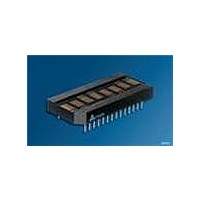
... High Efficiency Red Green High Efficiency Green Soft Orange DESCRIPTION The HDSP2110S (Red), HDSP2111S (Yellow), HDSP2112S (High Efficiency Red), HDSP2113S (Green), HDSP2114S (High Efficiency Green), and HDSP2115S (Soft Orange) are eight digit dot matrix, alphanumeric Intelligent Display devices. The 0.20 inch high digits are packaged in a rugged, high qual- ity, optically transparent, 0 ...
Page 2
HSDP2110S, HSDP2111S, HSDP2112S, HSDP2113S, HSDP2114S, HSDP2115S Ordering Information Type Color of Emission HSDP2110S red HSDP2111S yellow HSDP2112S high efficiency red HSDP2113S green HSDP2114S high efficiency green HSDP2115S soft orange Package Outlines Part Number HDSP211X Z OSRAM 4.79 (0.189) 5.34 (0.210) ...
Page 3
HSDP2110S, HSDP2111S, HSDP2112S, HSDP2113S, HSDP2114S, HSDP2115S Maximum Ratings at 25°C Parameter Operating temperature range Storage temperature range V DC Supply Voltage, to GND CC (max. voltage with no LEDs on) Input Voltage Levels All inputs Operating Voltage GND ...
Page 4
... T acs CE RD D0-D7 Switching Specifications (over operating temperature range and V Symbol Description T Display Access Time—Write acc T Display Access Time—Read acc T Address Setup Time to CE acs T Chip Enable Active Time—Write ce T Chip Enable Active Time—Read ce T Address Hold Time to CE ...
Page 5
... Determine the correct address for each display. • Use CE from an address decoder to select the correct display. • Select one of the Displays to provide the clock for the other displays. Connect CLKSEL to V • Tie CLKSEL to ground on other displays. • Use RTS to synchronize the blinking between the displays. ...
Page 6
... FM, Digit Multiplex Frequency Blinking Rate Clock I/O Buss Loading Clock Out Rise Time Clock Out Fall Time Notes average value measured with the display at full brightness. Peak I CC Recommended Operating Conditions (T Parameter Symbol Supply Voltage V CC Input Voltage Low V IL Input Voltage High ...
Page 7
... Definition Analog Ground for LED drivers Digital Ground for internal drivers Enables access to the display A low will read data from the display low. If read from display is not required, Data input LSB Data input — — Data input Data input Data input ...
Page 8
HSDP2110S, HSDP2111S, HSDP2112S, HSDP2113S, HSDP2114S, HSDP2115S Character Set ASCII CODE HEX ...
Page 9
... HDSP211X display for the synchronization of blinking for multiple dis- plays. The Display Multiplexer controls the Row Drivers so no additional logic is required for a display system. The Display has eight digits. Each digit has 35 LEDs clustered into dot matrix. 9 Column Drivers ...
Page 10
... The Character RAM bit RAM with each of the eight locations corresponding to a digit on the display. Digit the left side of the display and digit the right side of the display. Address lines, A2–A0 select the digit address with A2 being the most significant bit and A0 being the least significant bit ...
Page 11
... A4 and A3 are ignored. The Flash RAM bit RAM with each bit corresponding to a digit address. Digit the left side of the display and digit the right side of the display. Address lines, A2–A0 select the digit address with A2 being the most signif- icant digit and A0 being the least significant digit ...
Page 12
... D0 To synchronize the flashing and blinking of multiple displays necessary for the display to use a common clock source and reset all the displays at the same time to start the internal counters at the same place. While RST is low, the display must not be accessed by RD nor WR ...
Page 13
... Clear Function 0 Normal Operation 1 Clear Flash RAM & Character RAM (Character RAM = 20 Hex) Clear Function X=don’t care Display Cycle Using Built-in ROM Example Display message “Showtime.” Digit 0 is leftmost—closest to pin 1. Logic levels: 0=Low, 1=High, X=Don’t care RST ...
Page 14
... HSDP2110S, HSDP2111S, HSDP2112S, HSDP2113S, HSDP2114S, HSDP2115S Displaying User Defined Character Example Load character “A” into UDC-5 and then display it in digit 2 Logic levels: 0=Low, 1=High, X=Don‘t care RST Electrical and Mechanical Considerations Voltage Transient Suppression For best results power the display and the components that inter- ...
Page 15
... Plastic filters can be improved further with anti-reflective coatings to reduce glare. The trade-off is fuzzy characters. Mounting the filters close to the display reduces this effect. Take care not to overheat the plastic filter by allowing for proper air flow. Optimal filter enhancements are gained by using circular polarized, anti-reflective, band-pass filters. The circular polarizing further enhances contrast by reducing the light that travels through the filter and reflects back off the display to less than 1%. Several filter manufacturers supply quality filter materials. Some of them are: Panelgraphic Corporation, W. Caldwell, NJ ...
Page 16
HSDP2110S, HSDP2111S, HSDP2112S, HSDP2113S, HSDP2114S, HSDP2115S Revision History: 2006-01-23 Previous Version: 2004-11-11 Page Subjects (major changes since last revision) all Lead free device ublished by P OSRAM Opto Semiconductors GmbH Wernerwerkstrasse 2, D-93049 Regensburg www.osram-os.com © All Rights Reserved. Attention ...