DLG1414 OSRAM Opto Semiconductors Inc, DLG1414 Datasheet - Page 10
DLG1414
Manufacturer Part Number
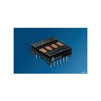
DLG1414
Description
LED Displays 5x7 Green 0.145 , 4-CHARACTER
Manufacturer
OSRAM Opto Semiconductors Inc
Datasheet
1.DLO1414.pdf
(10 pages)
Specifications of DLG1414
Display Type
Dot Matrix
Emitting Color
Green
Number Of Digits
4
Digit Size (in)
.145in
Viewing Area Height (mm)
3.66mm
Viewing Area Length (mm)
2.34mm
Package Type
DIP
Operating Supply Voltage (min)
4.5V
Operating Supply Voltage (typ)
5V
Operating Supply Voltage (max)
5.5V
Operating Temperature Classification
Industrial
Operating Temp Range
-40C to 85C
Mounting
Through Hole
Pin Count
12
Total Thickness (mm)
6.1mm
Opto Display Type
Panel
Pattern Type
Dot Matrix
Size / Dimension
0.80" L x 0.70" W x 0.24" H (20.32mm x 17.78mm x 6.10mm)
Color
Green
Configuration
5 x 7
Character Size
0.145 in
Illumination Color
Green
Wavelength
565 nm
Maximum Operating Temperature
+ 85 C
Minimum Operating Temperature
- 40 C
Luminous Intensity
70 ucd
Viewing Area (w X H)
2.34 mm x 3.66 mm
Lead Free Status / RoHS Status
Compliant
Voltage - Forward (vf) Typ
-
Millicandela Rating
-
Internal Connection
-
Lead Free Status / Rohs Status
Details
Other names
Q1757650
Q68000-A8093
Q68000-A8093
Q68000A8093
Q68000-A8093
Q68000-A8093
Q68000A8093
Available stocks
Company
Part Number
Manufacturer
Quantity
Price

Part Number:
DLG1414
Manufacturer:
SIEMENS/西门子
Quantity:
20 000
Company:
Part Number:
DLG1414LC
Manufacturer:
YAMAICHI
Quantity:
1 243


Design Considerations
For details on design and applications of the DLX1414 using
standard bus configurations in multiple display systems, or parallel
I/O devices, such as the 8255 with an 8080 or memory mapped
addressing on processors such as the 8080, Z80, 6502, 8748, or
6800, refer to Appnote 15 at www.osram-os.com.
Electrical & Mechanical Considerations
Voltage Transient Suppression
We strongly recommend that the same power supply be used for
the display and the components that interface with the display to
avoid logic inputs higher than V
cause transients in the power supply line while they change dis-
play states. The common practice is to place .01 mF capacitors
close to the displays across V
and one 10 mF capacitor for every second display.
ESD Protection
The metal gate CMOS IC of the DLX1414 is extremely immune to
ESD damage. However, users of these devices are encouraged to
take all the standard precautions, normal for CMOS components.
These include properly grounding personnel, tools, tables, and
transport carriers that come in contact with unshielded parts.
Where these conditions are not, or cannot be met, keep the leads
of the device shorted together or the parts in anti-static packaging.
Soldering Considerations
The DLX1414 can be hand soldered with SN63 solder using a
grounded iron set to 260×C.
Wave soldering is also possible following these conditions: Preheat
that does not exceed 93×C on the solder side of the PC board or a
package surface temperature of 85×C. Water soluble organic acid
flux (except carboxylic acid) or rosin-based RMA flux without
alcohol can be used.
Wave temperature of 245×C ±5×C with a dwell between 1.5 sec. to
3.0 sec. Exposure to the wave should not exceed temperatures
above 260×C for five seconds at 0.063" below the seating plane.
The packages should not be immersed in the wave.
Post Solder Cleaning Procedures
The least offensive cleaning solution is hot D.I. water (60 ×C) for
less than 15 minutes. Addition of mild saponifiers is acceptable. Do
not use commercial dishwasher detergents.
For faster cleaning, solvents may be used. Carefully select sol-
vents as some may chemically attack the nylon package. Maxi-
mum exposure should not exceed two minutes at elevated
temperatures. Acceptable solvents are TF (trichlorotrifluorethane),
TA, 111 Trichloroethane, and unheated acetone.
Note: Acceptable commercial solvents are: Basic TF, Arklone P,
Genesolve D, Blaco-tron TF, Genesolve DA, and Blaco-tron TA.
Unacceptable solvents contain alcohol, methanol, methylene chlo-
ride, ethanol, TP35, TCM, TMC, TMS+, TE, or TES. Since many
commercial mixtures exist, contact a solvent vendor for chemical
composition information. Some major solvent manufacturers are:
Allied Chemical Corporation, Specialty Chemical Division, Morris-
town, NJ; Baron-Blakeslee, Chicago, IL; Dow Chemical, Midland,
MI; E.I. DuPont de Nemours & Co., Wilmington, DE.
For further information refer to Appnotes 18 and 19 at
www.osram-os.com.
An alternative to soldering and cleaning the display modules is to
use sockets. Eighteen pin DIP sockets .600" wide with .100" cen-
ters work well for single displays. Multiple display assemblies are
best handled by longer SIP sockets or DIP sockets when available
for uniform package alignment. Socket manufacturers are Aries
2006-01-23
CC
CC
and GND, one for each display,
. Additionally, the LEDs may
10
Electronics, Inc., Frenchtown, NJ; Garry Manufacturing, New Brun-
swick, NJ; Robinson-Nugent, New Albany, IN; and Samtec Elec-
tronic Hardware, New Albany, IN.
For further information refer to Appnote 22 at www.osram-os.com.
Optical Considerations
The .145" high characters of the DLX1414 gives readability up to
eight feet. The user can build a display that enhances readability
over this distance by proper filter selection.
Using filters emphasizes the contrast ratio between a lit LED and
the character background. This will increase the discrimination of
different characters. The only limitation is cost. Remember to take
into consideration the ambient lighting environment for the best
cost/benefit ratio for filters.
Incandescent (with almost no green) or fluorescent (with almost no
red) lights do not have the flat spectral response of sunlight. Plas-
tic band-pass filters are an inexpensive and effective way to
strengthen contrast ratios. The DLR1414 is a standard red display
and should be matched with long wavelength pass filter in the 600
nm to 620 nm range. For displays of multiple colors, neutral den-
sity grey filters offer the best compromise.
The DLO1414 is a high efficiency red display and should be
matched with a long wavelength pass filter in the 570 nm to
590 nm range. The DLG1414 should be matched with a yel-
low-green band-pass filter that peaks at 565 nm. For displays of
multiple colors, neutral density gray filters offer the best compro-
mise.
Additional contrast enhancement can be gained by shading the
displays. Plastic band-pass filters with built-in louvers offer the next
step up in contrast improvement. Plastic filters can be improved
further with anti-reflective coatings to reduce glare. The trade-off is
fuzzy characters. Mounting the filters close to the display reduces
this effect. Take care not to overheat the plastic filter by allowing for
proper air flow.
Optimal filter enhancements are gained by using circular polar-
ized, anti-reflective, band-pass filters. The circular polarizing fur-
ther enhances contrast by reducing the light that travels through
the filter and reflects back off the display to less than 1%.
Several filter manufacturers supply quality filter materials. Some of
them are: Panelgraphic Corporation, W. Caldwell, NJ; SGL Homa-
lite, Wilmington, DE; 3M Company, Visual Products Division, St.
Paul, MN; Polaroid Corporation, Polarizer Division, Cambridge,
MA; Marks Polarized Corporation, Deer Park, NY, Hoya Optics,
Inc., Fremont, CA.
One last note on mounting filters: recessing displays and bezel
assemblies is an inexpensive way to provide a shading effect in
overhead lighting situations. Several bezel manufacturers are:
R.M.F. Products, Batavia, IL; Nobex Components, Griffith Plastic
Corp., Burlingame, CA; Photo Chemical Products of California,
Santa Monica, CA; I.E.E.-Atlas, Van Nuys, CA.
Refer to Appnote 23 at www.osram-os.com.
Published by
OSRAM Opto Semiconductors GmbH
Wernerwerkstrasse 2, D-93049 Regensburg
www.osram-os.com
© All Rights Reserved.
DLR1414, DLO1414, DLG1414
Related parts for DLG1414
Image
Part Number
Description
Manufacturer
Datasheet
Request
R

Part Number:
Description:
INTELLIGENT DISP 4CHAR 5X7 HERED
Manufacturer:
OSRAM Opto Semiconductors Inc
Datasheet:

Part Number:
Description:
DISPLAY 8DIGIT CERAMIC GREEN
Manufacturer:
OSRAM Opto Semiconductors Inc
Datasheet:

Part Number:
Description:
EMITTER IR 950NM 5MM SMD RADIAL
Manufacturer:
OSRAM Opto Semiconductors Inc
Datasheet:

Part Number:
Description:
LED TOPLED GREEN 570NM 2-PLCC
Manufacturer:
OSRAM Opto Semiconductors Inc
Datasheet:

Part Number:
Description:
INTERRUPTER RELFECT W/FILTR SMD
Manufacturer:
OSRAM Opto Semiconductors Inc
Datasheet:

Part Number:
Description:
Q65110A4321_SIDELED PURE GREEN EOL150407
Manufacturer:
OSRAM Opto Semiconductors Inc
Datasheet:
Part Number:
Description:
Q65110A1202_RO DETECTOR 3/5MM_TR_RO
Manufacturer:
OSRAM Opto Semiconductors Inc
Datasheet:

Part Number:
Description:
PHOTODIODE 900NM 3MM W/FILTER
Manufacturer:
OSRAM Opto Semiconductors Inc
Datasheet:

Part Number:
Description:
PHOTODIODE 860NM 3MM CLEAR
Manufacturer:
OSRAM Opto Semiconductors Inc
Datasheet:
Part Number:
Description:
INTELLIGENT DISP 4CHAR 5X7 HERED
Manufacturer:
OSRAM Opto Semiconductors Inc
Datasheet:
Part Number:
Description:
LED TOPLED GREEN 570NM 2-PLCC
Manufacturer:
OSRAM Opto Semiconductors Inc
Datasheet:
Part Number:
Description:
PHOTODIODE 900NM 3MM W/FILTER
Manufacturer:
OSRAM Opto Semiconductors Inc
Datasheet:

Part Number:
Description:
PHOTODIODE 850NM THRU-HOLE
Manufacturer:
OSRAM Opto Semiconductors Inc
Datasheet:

Part Number:
Description:
PHOTODIODE 880NM W/FILTER SMD
Manufacturer:
OSRAM Opto Semiconductors Inc
Datasheet: