E2K-X8MY1 5M Omron, E2K-X8MY1 5M Datasheet
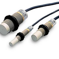
E2K-X8MY1 5M
Specifications of E2K-X8MY1 5M


Related parts for E2K-X8MY1 5M


E2K-X8MY1 5M Summary of contents
Page 1
... Accessories (Order Separately) Mounting Brackets http://www.ia.omron.com/ Output configuration DC 3-wire, NPN AC 2-wire DC 3-wire, NPN AC 2-wire DC 3-wire, NPN 2-wire (c)Copyright OMRON Corporation 2007 All Rights Reserved. Model Operation mode NO NC E2K-X4ME1 E2K-X4ME2 E2K-X4MY1 E2K-X4MY2 E2K-X8ME1 E2K-X8ME2 E2K-X8MY1 E2K-X8MY2 E2K-X15ME1 E2K-X15ME2 E2K-X15MY1 E2K-X15MY2 1 ...
Page 2
... E Models (DC switching models): A full-wave rectification power supply of 24 VDC 20% (average value) can be used. http://www.ia.omron.com/ E2K-X8ME@, E2K-X8MY 10 5 Refer to the timing charts under I/O Circuit Diagrams on page 4 for details times each and Z directions Approx. 145 g Instruction manual (c)Copyright OMRON Corporation 2007 All Rights Reserved. E2K-X E2K-X15ME@, E2K-X15MY 10 Operating/Storage (with no icing or condensation) Approx. 205 g 2 ...
Page 3
... Grounded metal plate 50 × 50 × E2K-X8M 6 4 E2K-X4M 2 0 −5 −20 −15 −10 − E2K-X4M Sensing Distance Y (mm) E2K-X8M Sensing Head E2K-X15M Sensing Head Influence of Sensing Object Size and Material E2K-X4M 5 d × Grounded metal 4 3 Non-grounded metal 2 1 Glass Phenol ...
Page 4
... Detection indicator (red) AC 2-Wire Models Operation Model mode Sensing object E2K-X4MY1 NO E2K-X8MY1 Load E2K-X15MY1 Operation indicator (red) Sensing object E2K-X4MY2 NC E2K-X8MY2 Load E2K-X15MY2 Operation indicator (red) http://www.ia.omron.com/ Residual Output Voltage E2K-X@MY@ at 100 VAC 120 Residual output voltage 100 ...
Page 5
... The maximum sensing distance of the E2K-X will be obtained if the object is made of grounded metal. There are objects that cannot be detected indirectly. Therefore, be sure to test the E2K trial operation with the objects before using the E2K-X in actual applications. Effects of a High-frequency Electromagnetic Field The E2K-X may malfunction if there is an ultrasonic washer, high- frequency generator, transceiver, or inverter nearby ...
Page 6
... OMRON Corporation 2007 All Rights Reserved. E2K-X (Unit: mm Indicator * 16.6 dia. *1 M18 × 1 Two clamping nuts Two washers 2 , Insulator diameter: 1.9 mm Insulator diameter: 1.9 mm), Model F (mm) E2K-X4ME@ +0.5 12.5 dia. 0 E2K-X4MY@ E2K-X8ME@ +0.5 18.5 dia. 0 E2K-X8MY@ E2K-X15ME@ +0.5 30.5 dia. E2K-X15MY ...
Page 7
... Brown − Sensor + Blue (c)Copyright OMRON Corporation 2007 All Rights Reserved. DC 2-Wire Sensors Load Brown Sensor Blue • DC 2-Wire Sensors • Even with the load short-circuit protection ...
Page 8
... Conduits, ducts, pre-wired, terminal wiring, ease of main- tenance and inspection mT* max. Do not use the Sensor at a level higher than 20 mT. Life: Power-ON time/frequency of use (c)Copyright OMRON Corporation 2007 All Rights Reserved. Peripheral metal Sensing distance Material, distance Fluctuation in tran- to Sensor, orien- sit point, allowable tation, etc ...
Page 9
... A Sensor is ready for detection within 100 ms after turning ON the power. If the load and Sensor are connected to separate power supplies, design the system so that the Sensor power turns ON first. (c)Copyright OMRON Corporation 2007 All Rights Reserved. Sensing object shape: Square d=30mm Reset ...
Page 10
... OFF It is recommend that leeway be included in the actual values used. For 12 VDC, use 15 kΩ or less and 450 mW or higher, and for 24 VDC, use 30 kΩ or less and 0 higher. (c)Copyright OMRON Corporation 2007 All Rights Reserved. AC power supply voltage Vs 2 (mW) ...
Page 11
... Loads with Large Inrush Current Loads, such as lamps or motors, that cause a large inrush weaken or damage the switching element. In this situation, use a relay. * E2K, TL-N@ higher ●Mounting Mounting the Sensor When mounting a Sensor, do not tap it with a hammer or otherwise subject it to excessive shock. This will weaken water resistance and may damage the Sensor ...
Page 12
... N: Number of Sensors that can be connected i: Leakage current of Proximity Sensor Example: When an MY (24-VDC) Relay is used as the load, the maximum number of Sensors that can be connected is 4. <TL-NY, TL-MY, E2K-@MY@, TL-T@Y> Load The above Proximity Sensors cannot be used in a sereis connection. If need- ed, connect through relays. ...
Page 13
... The residual voltage of the E2E-XD-M1J 3-Wire Sensors Operation can be reversed with the signal input switch on the S3D2. (c)Copyright OMRON Corporation 2007 All Rights Reserved. Description Example: A maximum of two Sensors can be used when an MY (24-VDC) Relay is used for the load ...
Page 14
... Do not under any circumstances attempt to disassemble or repair the product. Quick Failure Check You can conveniently check for failures by connecting the E39-VA Handy Checker to check the operation of the Sensor. http://www.ia.omron.com/ Proximity Sensors Technical Guide (c)Copyright OMRON Corporation 2007 All Rights Reserved. C-8 ...
Page 15
... Please read and understand this catalog before purchasing the products. Please consult your OMRON representative if you have any questions or comments. WARRANTY OMRON's exclusive warranty is that the products are free from defects in materials and workmanship for a period of one year (or other period if specifi ed) from date of sale by OMRON. OMRON MAKES NO WARRANTY OR REPRESENTATION, EXPRESS OR IMPLIED, REGARDING NON-INFRINGEMENT, MERCHANTABILITY, OR FITNESS FOR PARTICULAR PURPOSE OF THE PRODUCTS ...