BAP51-02 NXP Semiconductors, BAP51-02 Datasheet - Page 2
BAP51-02
Manufacturer Part Number
BAP51-02
Description
General purpose PIN diode in a SOD523 ultra small SMD plastic package
Manufacturer
NXP Semiconductors
Datasheet
1.BAP51-02.pdf
(6 pages)
Specifications of BAP51-02
Configuration
Single
Forward Current
50mA
Forward Voltage
1.1V
Power Dissipation
715mW
Operating Temperature Classification
Military
Package Type
I-IGIA
Mounting
Surface Mount
Maximum Series Resistance @ Minimum If
9@0.5mAOhm
Maximum Series Resistance @ Maximum If
2.5@10mAOhm
Operating Temperature (max)
150C
Operating Temperature (min)
-65C
Pin Count
2
Lead Free Status / RoHS Status
Compliant
Available stocks
Company
Part Number
Manufacturer
Quantity
Price
Company:

Part Number:
BAP51-02
Manufacturer:
NXP
Quantity:
51 000
Part Number:
BAP51-02+115
Manufacturer:
NXP/恩智浦
Quantity:
20 000
Company:
Part Number:
BAP51-02,115
Manufacturer:
HARRIS
Quantity:
1 539


NXP Semiconductors
FEATURES
APPLICATIONS
DESCRIPTION
General purpose PIN diode in a SOD523 ultra small SMD
plastic package.
LIMITING VALUES
In accordance with the Absolute Maximum Rating System (IEC 60134).
ELECTRICAL CHARACTERISTICS
T
Note
1. Guaranteed on AQL basis: inspection level S4, AQL 1.0.
THERMAL CHARACTERISTICS
V
I
P
T
T
V
V
I
C
r
R
j
F
SYMBOL
R
SYMBOL
SYMBOL
D
Low diode capacitance
Low diode forward resistance.
General RF applications.
stg
j
R
tot
= 25 C unless otherwise specified.
F
R
General purpose PIN diode
d
th j-s
continuous reverse voltage
continuous forward current
total power dissipation
storage temperature
junction temperature
forward voltage
reverse voltage
reverse current
diode capacitance
diode forward resistance
thermal resistance from junction to soldering point
PARAMETER
PARAMETER
PARAMETER
Rev. 03 - 2 January 2008
I
I
V
V
V
V
I
I
I
T
F
R
F
F
F
s
R
R
R
R
= 50 mA
= 0.5 mA; f = 100 MHz; note 1
= 1 mA; f = 100 MHz; note 1
= 10 mA; f = 100 MHz; note 1
= 10 A
= 90 C
= 50 V
= 0; f = 1 MHz
= 1 V; f = 1 MHz
= 5 V; f = 1 MHz
CONDITIONS
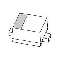
PINNING
handbook, halfpage
CONDITIONS
Marking code: K1.
Fig.1 Simplified outline (SOD523) and symbol.
PIN
1
2
1
T op view
50
MIN.
cathode
anode
2
MAM405
0.95
0.4
0.3
0.2
5.5
3.6
1.5
MIN.
TYP.
65
65
Product specification
VALUE
DESCRIPTION
85
BAP51-02
60
50
715
+150
+150
1.1
100
0.55
0.35
9
6.5
2.5
MAX.
MAX.
2 of 6
UNIT
K/W
V
mA
mW
V
V
nA
pF
pF
pF
UNIT
UNIT
C
C
Related parts for BAP51-02
Image
Part Number
Description
Manufacturer
Datasheet
Request
R

Part Number:
Description:
Two planar PIN diodes in series configuration in a SOT323 small SMD plastic package
Manufacturer:
NXP Semiconductors
Datasheet:
Part Number:
Description:
Two planar PIN diodes in common anode configuration in a SOT323 small SMD plastic package
Manufacturer:
NXP Semiconductors
Datasheet:

Part Number:
Description:
DIODE PIN GP 50V 50MA SOD-323
Manufacturer:
NXP Semiconductors
Datasheet:

Part Number:
Description:
Two planar PIN diodes in common cathode configuration in a SOT323 small SMD plastic package
Manufacturer:
NXP Semiconductors
Datasheet:

Part Number:
Description:
General purpose PIN diode in a SOD323 small plastic SMD package
Manufacturer:
NXP Semiconductors
Datasheet:


Part Number:
Description:
Bap51-02 General Purpose Pin Diode
Manufacturer:
NXP Semiconductors
Datasheet:
Part Number:
Description:
Bap51-04w General Purpose Pin Diode
Manufacturer:
NXP Semiconductors
Datasheet:

Part Number:
Description:
DIODE PIN GP 50V 50MA SOT-323
Manufacturer:
NXP Semiconductors
Datasheet:

Part Number:
Description:
DIODE PIN GP 50V 50MA SOT323
Manufacturer:
NXP Semiconductors
Datasheet:

Part Number:
Description:
General purpose PIN diode
Manufacturer:
NXP [NXP Semiconductors]
Datasheet:
Part Number:
Description:
DIODE PIN ATTENUATOR 60V 2SOD523 T/R
Manufacturer:
Philips Semiconductors / NXP Semiconductors
Part Number:
Description:
General purpose PIN diode - Application: Wireless ; C<sub>d</sub> typ.: 0.35@VR=5V and F=1MHz max0.4@VR=0V and F=1MHz0.55@VR=1V and F=1MHz max pF; Configuration: Single ; Diode type: General Purpose PINs ; Function: Diodes ; I<sub>F
Manufacturer:
NXP Semiconductors / Philips Semiconductors
Part Number:
Description:
PIN, Diode, Attenuator, Single, 50V, VHF, SOD-323 Package, 2Pin, Tape and Reel
Manufacturer:
Philips Semiconductors / NXP Semiconductors