646547-1 TE Connectivity, 646547-1 Datasheet - Page 9
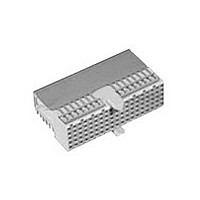
646547-1
Manufacturer Part Number
646547-1
Description
Conn Hard Metric F 110 POS 2mm Press Fit RA Thru-Hole
Manufacturer
TE Connectivity
Type
Hard Metricr
Specifications of 646547-1
Pitch
2 mm
Number Of Rows
5
Number Of Contacts
110
Termination Method
Press Fit
Mounting
Through Hole
Contact Plating
Gold Over Nickel
Pitch (mm)
2mm
Gender
F
Body Orientation
Right Angle
Number Of Contact Rows
5
Mounting Style
Through Hole
Contact Material
Phosphor Bronze
Housing Material
Polyester
Product Length (mm)
49.9mm
Rohs Compliant
YES
Product Type
Connector
Connector Type
Connector Assembly
Pcb Mounting Orientation
Right Angle
Board Mount
Fixed Board
Module Length (mm [in])
49.90 [1.966]
Crosstalk Version
Standard
Shielded
Yes
Interface Type
2mm HM
Number Of Positions
125
Grounding Contact
Without
Rows Loaded
Fully Loaded
Contact Configuration
ACTION PIN Post
Feedthrough Post Length (mm [in])
3.30 [0.130]
Compactpci
No
Contact Plating, Mating Area, Material
Gold
Contact Base Material
Phosphor Bronze
Connector Style
Receptacle
Mating Alignment
Without
Rohs/elv Compliance
RoHS compliant, ELV compliant
Lead Free Solder Processes
Not relevant for lead free process
Rohs/elv Compliance History
Always was RoHS compliant
Lead Free Status / RoHS Status
Compliant


Connector Stacking
Connectors can be stacked
together without change of
contact pitch ensuring that
the end features shown
below nest together.
Guiding features are pro-
vided to align connector
pairs and avoid contact
damage. IEC 61076-4-101
dictates that connectors are
end stacked as shown in
the adjacent first five
columns, with B modules
located between modules
with location/guiding fea-
tures. An alternative guiding
device can be used
instead, such as the guide
pin (page 55).
Types C and N are intended
for use at a column end.
Universal Power Module
connectors can be located
at any position. Special
arrangements must be
made when stacking 8 row
to 5 row.
The diagrams show typical
arrangements but others
are possible.
ACTION PIN Contacts
Details of the pcb hole size
and finish apply to all
ACTION PIN contacts.
IEC 61076-4-101 specifies
true position of holes to
within 0.1 [.004]. For
feedthrough posts, true
position within 0.05 [.002]
to minimize out-of-position
post tips could be used.
A new contact can be
inserted into the same hole
three times without damage
should repair or replace-
ment be necessary.
Catalog 65911
Revised 7-05
www.tycoelectronics.com
Dimensions are in millimeters
and inches unless otherwise
specified. Values in brackets
are standard equivalents.
A
Contacts
AMP Z-PACK 2mm HM Hard Metric
Interconnection System
Connector Configurations
Daughtercard Spacing
Minimum spacing between columns is —
5 row
5 row cable conns
5 row EMI/RFI shields
8 row
AMP ACTION PIN Press-fit Contact Interconnection
Signal
110
A
C
Contacts
Signal
165
*
reference purposes only.
Dimensions are shown for
Specifications subject
to change.
A
A
16.00 [.630]
18.00 [.709]
20.00 [.787]
22.00 [.866]
Contacts
Signal
220
**
Annular Ring, Ø 1.0 [.039]
Drilled Hole Diameter, Ø 0.7 ± 0.025 [.0276 ± .001]
Prior to Plating
Cu Plating 0.025 - 0.050 [.001 - .002]
SnPb Plating Optional
0.004 - 0.010 [.0002 - .0004]
Finished Hole Ø 0.55 - 0.65 [.0217 - .0256]
M
A
N
6 Special
Contacts
Signal,
165
A
B
A
B
C
USA: 1-800-522-6752
Canada: 1-905-470-4425
Mexico: 01-800-733-8926
C. America: 52-55-5-729-0425
Contacts
Signal
525
*
A
B
L
L
B
12 Special
Contacts
Signal,
360
**
Guide
Guide
Pin
Pin
B
L
B
**
**
to different degrees to accommo-
date hole tolerances max. diago-
Two spring members compress
Min. Hole ø
0.55 [.0217]
South America: 55-11-3611-1514
Hong Kong: 852-2735-1628
Japan: 81-44-844-8013
UK: 44-141-810-8967
Overall length fits Eurocard
board sizes
Overall length fits ETSI
board sizes
A
B
A
nal 0.84 [.033] dia.
Max. Hole ø
0.65 [.0256]
9
Related parts for 646547-1
Image
Part Number
Description
Manufacturer
Datasheet
Request
R

Part Number:
Description:
Printers THERMAL PRINTER HS-SLEEVE MARKER
Manufacturer:
TE Connectivity


Part Number:
Description:
High Speed / Modular Connectors 30P HEADER ASSY
Manufacturer:
TE Connectivity
Datasheet:

Part Number:
Description:
High Speed / Modular Connectors REC 6X005P R/A LT B-PLANE HS3
Manufacturer:
TE Connectivity
Datasheet:

Part Number:
Description:
High Speed / Modular Connectors 2MM HM RCPT 50P R/A AU
Manufacturer:
TE Connectivity
Datasheet:

Part Number:
Description:
High Speed / Modular Connectors 2MM HM RCPT 50P R/A AU
Manufacturer:
TE Connectivity
Datasheet:


Part Number:
Description:
Manufacturer:
TE Connectivity
Datasheet:


Part Number:
Description:
Manufacturer:
TE Connectivity
Datasheet:

Part Number:
Description:
Manufacturer:
TE Connectivity
Datasheet:

Part Number:
Description:
Manufacturer:
TE Connectivity
Datasheet: