EZA-DT63AAAJ Panasonic - ECG, EZA-DT63AAAJ Datasheet - Page 8
EZA-DT63AAAJ
Manufacturer Part Number
EZA-DT63AAAJ
Description
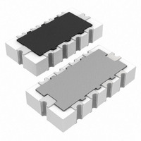
RC NETWORK 1K OHM/100PF 5% SMD
Manufacturer
Panasonic - ECG
Series
EZADTr
Datasheet
1.EZA-CT00AAAJ.pdf
(9 pages)
Specifications of EZA-DT63AAAJ
Resistance (ohms)
1K
Capacitance
100pF
Tolerance
Resistance ±5%, Capacitance +30%, -20%
Power (watts)
0.063W, 1/16W
Package / Case
1206 (3216 Metric)
Resistance In Ohms
1.00K
Lead Free Status / RoHS Status
Lead free / RoHS Compliant
Other names
EZADT63AAAJ
PDT63TR
PDT63TR


■
The following are precautions for individual products. Please also refer to the common precautions shown on page 4
of this catalog.
1. Take measures against mechanical stress during and after mounting of Chip RC Networks (hereafter called the RC networks)
2. Do not use halogen-based or other high-activity fl ux. Otherwise, the residue may impair the RC networks' performance
3. Perform suffi cient preheating so that the difference of the solder temperature and the RC networks chip surface
4. When soldering with a soldering iron, never touch the RC networks' bodies with the tip of the soldering iron. When
5. As the amount of applied solder becomes larger, the mechanical stress applied to the RC networks increases, causing
6. Do not apply shock to the RC networks or pinch them with a hard tool (e.g. pliers and tweezers). Otherwise, the RC networks'
7. Avoid excessive bending of printed circuit boards in order to protect the RC networks from abnormal stress.
8. The static capacitance may decrease by a few percent from the time of shipment due to the characteristics peculiar to
Design and specifi cations are each subject to change without notice. Ask factory for the current technical specifi cations before purchase and/or use.
Should a safety concern arise regarding this product, please be sure to contact us immediately.
Safety Precautions
Recommended Soldering Conditions
Recommendations and precautions are described below.
● Recommended soldering conditions for refl ow
● Flow Soldering
so as not to damage their electrodes and protective coatings.
Be careful not to misplace the RC networks on the land patterns. Otherwise, solder bridging may occur.
and/or reliability.
temperature becomes 100 °C or less. Maintain the temperature difference within 100 °C during rapid cooling by
immersion into solvent after soldering.
using a soldering iron with a high temperature tip, fi nish soldering as quickly as possible (within three seconds at
350 °C max.).
problems such as cracks and faulty characteristics. Avoid applying an excessive amounts of solder.
protective coatings and bodies may be chipped, affecting their performance.
dielectric materials having a high dielectric constant.
·R efl ow soldering shall be performed a maximum of
·Please contact us for additional information when
·Please measure the temperature of the terminals and
two times.
used in conditions other than those specifi ed.
study every kind of solder and printed circuit board
for solderability be fore actual use.
We do not recommend fl ow soldering to the prod uct, because solder bridging may occur due to the
narrow pitch of the terminals and the characteristics of the product may be badly affected when using
adhesive to affi x it to a circuit board.
Preheating
Peak
Time
Heating
– 268 –
For soldering (Example : Sn/Pb)
For lead-free soldering (Example : Sn/Ag/Cu)
This product has circuits on both sides. Therefore, do not use
adhesives because they may impair the products characteristics.
Preheating
Main heating
Peak
Preheating
Main heating
Peak
140 °C to 160 °C
150 °C to 180 °C
Above 200 °C
Above 230 °C
Temperature
Temperature
max. 260 °C
235 ± 5 °C
Chip RC Networks
60 s to 120 s
60 s to120 s
30 s to 40 s
30 s to 40 s
max. 10 s
max. 10 s
Time
Time
00
Sep. 2010
Related parts for EZA-DT63AAAJ
Image
Part Number
Description
Manufacturer
Datasheet
Request
R


Part Number:
Description:
MICROPHONE OMNI 6X2.2MM W/CAP
Manufacturer:
Panasonic - ECG
Datasheet:

Part Number:
Description:
CAP .0018UF 16V PPS FILM 0603 5%
Manufacturer:
Panasonic - ECG

Part Number:
Description:
CAP .01UF 100V PEN FILM 1210 5%
Manufacturer:
Panasonic - ECG
Datasheet:

Part Number:
Description:
CAP .1F 5.5V GOLD SD VERTICAL
Manufacturer:
Panasonic - ECG
Datasheet:

Part Number:
Description:
SUR ABSORBER 14MM 39V 1000A ZNR
Manufacturer:
Panasonic - ECG
Datasheet:

Part Number:
Description:
FILTER LINE 23.3MH 2A
Manufacturer:
Panasonic - ECG
Datasheet:

Part Number:
Description:
BEAD CORE 600 OHM 100MA 0603 SMD
Manufacturer:
Panasonic - ECG
Datasheet:

Part Number:
Description:
SAW FILTER PCS 1960 MHZ 50/150
Manufacturer:
Panasonic - ECG
Datasheet:
Part Number:
Description:
SAW FILTER WCDMA 1950 MHZ 50/50
Manufacturer:
Panasonic - ECG
Datasheet:
Part Number:
Description:
SAW FILTER EGSM 942 MHZ 50/150
Manufacturer:
Panasonic - ECG
Datasheet:
Part Number:
Description:
SAW FILTER DCS 1842 MHZ 50/150
Manufacturer:
Panasonic - ECG
Datasheet:
Part Number:
Description:
POT 1.0M OHM 3MM SEALED SMD 3 TT
Manufacturer:
Panasonic - ECG
Datasheet:

Part Number:
Description:
MODULE POWER DC/DC 48V/28V 600W
Manufacturer:
Panasonic - ECG
Datasheet:
Part Number:
Description:
RES ARRAY 22 OHM 5% 4 RES SMD
Manufacturer:
Panasonic - ECG
Datasheet: