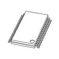
UJA1065TW/3V0-T NXP Semiconductors, UJA1065TW/3V0-T Datasheet - Page 12

UJA1065TW/3V0-T
Manufacturer Part Number
UJA1065TW/3V0-T
Description
Network Controller & Processor ICs HI SPEED CAN SYSTEM
Manufacturer
NXP Semiconductors
Datasheet
1.UJA1065TW3V0-T.pdf
(76 pages)
Specifications of UJA1065TW/3V0-T
Number Of Transceivers
1
Power Down Mode
Standby
Operating Supply Voltage (min)
5.5V
Supply Current
10mA
Operating Temperature (max)
125C
Operating Temperature (min)
-40C
Operating Temperature Classification
Automotive
Mounting
Surface Mount
Product
Controller Area Network (CAN)
Data Rate
20 Kbps
Supply Voltage (max)
27 V, 52 V
Supply Voltage (min)
5.5 V
Supply Current (max)
10 mA
Maximum Operating Temperature
+ 125 C
Minimum Operating Temperature
- 40 C
Mounting Style
SMD/SMT
Package / Case
HTSSOP EP
Lead Free Status / RoHS Status
Compliant
Other names
UJA1065TW/3V0,518
NXP Semiconductors
UJA1065_7
Product data sheet
6.2.7 Flash mode
6.3 On-chip oscillator
6.4 Watchdog
Flash mode can only be entered from Normal mode by entering a specific Flash mode
entry sequence. This fail-safe control sequence comprises three consecutive write
accesses to the Mode register, within the legal windows of the watchdog, using the
operating mode codes 111, 001 and 111 respectively. As a result of this sequence, the
SBC will enter Start-up mode and perform a system reset with the related reset source
information (bits RSS[3:0] = 0110).
From Start-up mode the application software now has to enter Flash mode within t
by writing Operating Mode code 011 to the Mode register. This feeds back a successfully
received hardware reset (handshake between the SBC and the microcontroller). The
transition from Start-up mode to Flash mode is possible only once after completing the
Flash entry sequence.
The application can also decide not to enter Flash mode but to return to Normal mode by
using the Operating Mode code 101 for handshaking. This erases the Flash mode entry
sequence.
The watchdog behavior in Flash mode is similar to its time-out behavior in Standby mode,
but Operating Mode code 111 must be used for serving the watchdog. If this code is not
used or if the watchdog overflows, the SBC immediately forces a reset and enters Start-up
mode. Flash mode is properly exited using the Operating Mode code 110 (leave Flash
mode), which results in a system reset with the corresponding reset source information.
Other Mode register codes will cause a forced reset with reset source code ‘illegal Mode
register code’.
The on-chip oscillator provides the clock signal for all digital functions and is the timing
reference for the on-chip watchdog and the internal timers.
If the on-chip oscillator frequency is too low or the oscillator is not running at all, there is
an immediate transition to Fail-safe mode. The SBC will stay in Fail-safe mode until the
oscillator has recovered to its normal frequency and the system receives a wake-up
event.
The watchdog provides the following timing functions:
The watchdog is clocked directly by the on-chip oscillator.
To guarantee fail-safe control of the watchdog via the SPI, all watchdog accesses are
coded with redundant bits. Therefore, only certain codes are allowed for a proper
watchdog service.
•
•
•
•
Start-up mode; needed to give the software the opportunity to initialize the system
Window mode; detects too early and too late accesses in Normal mode
Time-out mode; detects a too late access, can also be used to restart or interrupt the
microcontroller from time to time (cyclic wake-up function)
Off mode; fail-safe shut-down during operation thus preventing any blind spots in the
system supervision
Rev. 07 — 25 February 2010
High-speed CAN/LIN fail-safe system basis chip
UJA1065
© NXP B.V. 2010. All rights reserved.
WD(init)
12 of 76


