41F Cinch Connectors, 41F Datasheet - Page 128
41F
Manufacturer Part Number
41F
Description
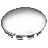
PLUG BUTTON .875" HOLE
Manufacturer
Cinch Connectors
Type
Body Plugr
Datasheet
1.41C.pdf
(282 pages)
Specifications of 41F
Color
Natural
Hole Diameter
0.875" (22.23mm)
Flange Diameter
1.062" (26.97mm)
Rohs Compliant
YES
Lead Free Status / RoHS Status
Lead free / RoHS Compliant
Panel Thickness
-
Lead Free Status / RoHS Status
Lead free / RoHS Compliant
Available stocks
Company
Part Number
Manufacturer
Quantity
Price
Company:

Part Number:
41F-1Z-C2-1
Manufacturer:
HGF
Quantity:
6
Company:
Part Number:
41FVX-RSM1-GSAN-G-ETF(S)
Manufacturer:
SHUN
Quantity:
994
Company:
Part Number:
41FXW-RSMI-G-G-TB
Manufacturer:
N/A
Quantity:
320


D-subminiature Metal Shell and All Plastic
Solder Cup and IDC
T* Series
Insulator Material: Glass-filled polyester (black), UL 94 V-O rated
Connector Shell: Steel with zinc plating and yellow chromate finish or
Contact Material: Phosphor bronze (stamped)
Contact Plating: Gold flash or 30µin. gold in mating area and gold
Operating Temperature: -65°C to + 125°C
Shock: 50G peak per MIL-STD-202, Method 213, Condition G
Vibration: 12 cycles in three perpendicular directions @ 10-2000Hz, per
Moisture Resistance: 90-95% relative humidity @ 40°C for 96 hours per
Individual Contact Insertion and
Durability: 500 mating cycles
Call Toll Free: 1 (800) 323-9612
Insulation Resistance:
Separation Force (minimum/maximum): 0.7 oz./12 oz.
Withstanding Voltage:
Offered in 9, 15, 25, and 37 position plugs and sockets.
Available in Solder Cup and IDC (insulation displacement) terminations for discrete wire.
Offered with .120 mounting holes.
Approvals:
•
•
See pages 4-5 thru 4-10 for standard dimensions, contact arrangements, and panel
mounting specifications.
Contact Resistance:
UL Recognized - Files E170218 (UL1977) and E130965 (UL1863).
CSA Approved - File LR31996.
Current Rating:
MIL-STD-202, Method 204, Condition D
flash on the remainder. All over nickel.
tin plating (grounding indents on plug)
MIL-STD-202, Method 103
Minimum 1000V RMS @ sea level
3 Amps
2.7 milliohms maximum
5000 megohms maximum (initial);
1000 megohms (minimum) after
environmental testing
4-34
Related parts for 41F
Image
Part Number
Description
Manufacturer
Datasheet
Request
R

Part Number:
Description:
Standard Card Edge Connectors CINCH BLK CARD GUIDE
Manufacturer:
Cinch Connectors

Part Number:
Description:
Automotive Connectors 18 Pos Black
Manufacturer:
Cinch Connectors
Part Number:
Description:
Automotive Connectors 30 Pos Black
Manufacturer:
Cinch Connectors
Part Number:
Description:
Automotive Connectors 30 Pos Black mates only w/ 60 Pin
Manufacturer:
Cinch Connectors
Part Number:
Description:
D-Subminiature Connectors 25C PLG S/CUP BASIC-D SERIES
Manufacturer:
Cinch Connectors

Part Number:
Description:
D-Subminiature Connectors 9C 2PC PLSTC BCKSHLL
Manufacturer:
Cinch Connectors

Part Number:
Description:
TERMINAL BLOCK JUMPER TYPE F
Manufacturer:
Cinch Connectors
Datasheet:
Part Number:
Description:
D-Subminiature Connectors MCHNED PIN 20-24AWG
Manufacturer:
Cinch Connectors
Datasheet:
Part Number:
Description:
Terminal Block,4 Contacts,0.44 Pitch
Manufacturer:
Cinch Connectors
Datasheet:

Part Number:
Description:
Terminal Block,8 Contacts,0.375 Pitch
Manufacturer:
Cinch Connectors
Datasheet: