H7EC-N-B Omron, H7EC-N-B Datasheet
H7EC-N-B
Specifications of H7EC-N-B
H7ECNB
Z861


H7EC-N-B Summary of contents
Page 1
... Display Display 7-segment LCD with backlight 7-segment LCD 7-segment LCD 7-segment LCD 2. Display None: 7-segment LCD without backlight H: 7-segment LCD with backlight 26 mm × 24.8 mm × 48 H7EC Part number Part number H7EC-NV-BH H7EC-NV-B H7EC-NFV-B H7EC-N-B Part number Y92S-36 Y92S-37 Y92F-75 Y92F-77B ...
Page 2
... Short-circuit residual voltage: 0.5 V max. Minimum open impedance: 750 kΩ min H7EC H7EC-N-B No-voltage input 30 Hz/1 kHz H7EC-N-B No voltage input Maximum short-circuit impedance: 10 kΩ max. Short-circuit residual voltage 0.5 V max. Minimum open impedance: 750 kΩ min kHz (Selectable) ...
Page 3
... I/O signal line (level 4) IP66, NEMA4 IP20 Approx H7EC H7EC-N-B 100 MΩ min. (at 500 VDC) between current-carrying metal parts and exposed non-current carrying metal parts 1,000 VAC, 50/60 Hz for 1 min between current-carrying metal parts and exposed non-current carrying metal parts 4 ...
Page 4
... H7EC Nomenclature J TOTAL COUNTER Counting speed switch For all models except for H7EC-NFV-j If the switch setting is changed, press the Reset Key on the front panel. Setting Counting speed (see note) Front panel 30 Hz (default setting) 1 kHz Terminal block Note: Perform switch setting before mounting to a control panel. ...
Page 5
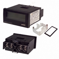
... H7EC Dimensions Unit: mm (inch) J H7EC-N 24 (0.94) Dimensions with Flush Mounting Bracket 35 (1.38) Installation J TERMINAL ARRANGEMENT Bottom view: View of the Total Counter rotated horizontally 180° Backlight Model Non-backlight Model Backlight 24 VDC Count Reset input input 44.8 (1.76) 48.5 48 (1.89) (1.91) 37 (1.46) ...
Page 6
... Open collector of a PNP transistor or Open collector of an NPN transistor Note: 1. Terminals 2 and 4 (input circuit and reset circuit) are functionally isolated. 2. Select input transistors according to the following: 6 H7EC Open collector of a PNP transistor Backlight 24 VDC Input Reset or Open collector of an NPN transistor Dielectric strength of the collector ≧ ...
Page 7
... Residual voltage in the output section of Proximity Sensors or Photoelectric Sensors becomes less than 0.5 V because the current flowing from terminals small as approx. 10 µA, allowing easy connection. 2. Select input transistors according to the following: Relay or Switch 7 H7EC Relay Relay Input Reset Terminals 2 and 4 are internally connected. or Switch or Switch ...
Page 8
... H7EC Accessories (Order Separately) An H7EC is supplied with a mounting bracket and nut. In addition, the Flush Mounting Adapters shown here allow the H7EC to be fitted to existing panel cutouts. J Y92F-75 FLUSH MOUNTING ADAPTER FOR 26 ¢ 45 RECTANGULAR CUTOUT Must be used with mounting bracket supplied with the Counter 31 24 ...
Page 9
... For this reason, be sure to tighten the screws for fixing the Flush Mounting Bracket. Screw for the Flush Mounting Bracket The wider side must Adapter face the panel. Panel 9 H7EC Reset Key Adapter screw section 0 Tighten the screw until the distance is within the range shown above. ...
Page 10
... OUT terminals that are connected with a diode as shown in the circuit diagram, the circuit indicated by the arrow will be formed when the device is turned OFF result, the H7EC may be reset or count by one recommended that such devices not be connected to the H7EC. ...
Page 11
... V peak or 60 VDC max. (Only the H7Ej-NVj-H has a backlight.) The terminals for counter input and reset input for AC/DC multi-voltage input models have basic insulation. Connect the reset input terminals to a device that does not have exposed current-carrying parts and has basic insulation for 240 VAC. 11 H7EC (2) ...
Page 12
... One East Commerce Drive Schaumburg, IL 60173 1-800-55-OMRON Cat. No. GC TMCN1 3/02 OMRON ON- -LINE Global -- http://www.omron.com USA -- http://www.omron.com/oei Canada -- http://www.omron.com/oci Specifications subject to c hange without notice. 12 H7EC OMRON CANADA, INC. 885 Milner Avenue Scarborough, Ontario M1B 5V8 416-286-6465 Printed i n U.S.A. ...