CUB5B000 Red Lion Controls, CUB5B000 Datasheet - Page 14
CUB5B000
Manufacturer Part Number
CUB5B000
Description
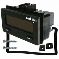
COUNTER/RATE IND DUAL RD/GN BKLT
Manufacturer
Red Lion Controls
Series
CUB5r
Type
Counter/Rate Indicatorr
Datasheet
1.CUB5RLY0.pdf
(16 pages)
Specifications of CUB5B000
Count Rate
20kHz
Number Of Digits/alpha
8
Input Type
Voltage, Switch Closure, Transistor Switch
Voltage - Supply
9 V ~ 28 V
Display Type
LCD Backlit
No. Of Digits / Alpha
8
Digit Height
11.7mm
Counting Speed
20kHz
Operating Temperature Range
-35°C To +75°C
Signal Input Type
Current
Display Mode
LCD Selectable Transmissive
Character Size
0.46"
Accuracy
±0.01% %
Connection Type
Screw
Counter Type
Electronic
Cut Out, Panel
2.68×1.3 "
Dimensions
2.95"L×1.86"W×1.54"H
Display Digit Height
0.46 "
Frequency, Operating
20 kHz (Max.)
Function
Counter/Rate Indicator
Material, Casing
Plastic
Memory Type
E2PROM
Mounting Type
Panel
Number Of Digits
8
Primary Type
Electronic
Range, Measurement
-9999999 to 999999
Special Features
Programmable
Standards
CE Approved
Temperature, Operating, Range
0 to 60 °C
Terminal Type
Screw Terminal
Termination
Screw Terminal
Voltage, Supply
9 to 28 VDC
Weight
85 g
Memory
Nonvolatile EEPROM
User Input
Programmable, Connect to Common to Activate Function
Rate Minimum Input Frequency
0.01 Hz
Rate Maximum Frequency
20 kHz
Operating Temperature
0 to 60°C
Panel Cutout
2.68" × 1.30"
Backlight Power
9-28VDC
Backlighting Color
Red Or Green
Rohs Compliant
Yes
Lead Free Status / RoHS Status
Lead free / RoHS Compliant
Output Type
-
Lead Free Status / Rohs Status
RoHS Compliant part
Other names
RLC122
Available stocks
Company
Part Number
Manufacturer
Quantity
Price
Company:

Part Number:
CUB5B000
Manufacturer:
Red Lion Controls
Quantity:
135


Sending Serial Commands and Data
command character must be constructed. A command string consists of a
command character, a value identifier, and numerical data (if writing data to the
meter) followed by a command terminator character, * or $.
Command Chart
Register Identification Chart
Command String Construction
does not respond with an error message to illegal commands. The following
procedure details construction of a command string:
1. The first 2 or 3 characters consist of the Node Address Specifier (N) followed
2. After the optional address specifier, the next character is the command character.
3. The next character is the register ID. This identifies the register that the
4. If constructing a value change command (writing data), the numeric data is
5. All command strings must be terminated with the string termination characters
Copy Procedure:
1. Connect the master and receiver using the appropriate copy cable.
2. Apply power to the meters. The receiving meter must be operating in the
3. On the master meter, enter programming mode and proceed to the Copy
4. During the copy process (~ 2 sec.), the master meter displays an upload
5. When copying is complete, the receiver displays the power-up sequence and
Command
ID
C
D
G
H
A
B
E
F
When sending commands to the meter, a string containing at least one
The command string must be constructed in a specific sequence. The meter
by a 1 or 2 character node address number. The node address number of the
meter is programmable. If the node address is 0, this command and the node
address itself may be omitted. This is the only command that may be used in
conjunction with other commands.
command affects. The P command does not require a register ID character. It
prints all the active selections chosen in the Print Options menu parameter.
sent next.
* or $. The meter does not begin processing the command string until this
character is received. See Command Response Time section for differences in
meter response time when using the * and $ terminating characters.
normal display mode (not programming mode).
Program Settings parameter in Module 5. Select
message (
This indicates successful communication between the master and receiver. If
the receiver message is not displayed, be sure the proper cable is connected.
returns to normal operating mode, programmed with all the same settings as
the master meter. The master remains at the
another receiver for copying.
N
V
R
P
T
Value Description
Counter A
Counter B
Rate
Scale Factor A
Scale Factor B
Setpoint 1
(Reset Output 1)
Setpoint 2
(Reset Output 2)
Counter A Count
Load Value
Description
Node (meter)
Address Specifier
Transmit Value
(read)
Value Change (write)
Reset
Block Print Request
(read)
UP-LOAd
) while the receiver displays a download message (
MNEMONIC
CTA
CTB
RTE
SFB
SP1
SP2
CLD
SFA
Notes
Address a specific meter. Must be followed
by one or two digit node address. Not
required when node address = 0.
Read a register from the meter. Must be
followed by a register ID character.
Write to register of the meter. Must be
followed by a register ID character and
numeric data.
Reset a count value or setpoint output. Must
be followed by a register ID character
Initiates a block print output. Registers in the
print block are selected in Print Options.
Applicable
Commands
T, V, R
T, V, R
T, V, R
T, V, R
T, V,
T, V
T, V
T
COPY
YES
Transmit Details (T and V)
8 digit positive/7 digit
negative (with minus sign)
7 digit, positive only
6 digit, positive only
6 digit, positive only
6 digit, positive only
per setpoint Assignment,
same as Counter or Rate
per setpoint Assignment,
same as Counter or Rate
8 digit positive/7 digit
negative (with minus sign)
prompt, ready to connect
to begin copying.
dn-LOAd
).
14
Command String Examples:
1. Node address = 17, Write 350 to the Setpoint 1 value
2. Node address = 5, Read Counter A, response time of 50 msec min
3. Node address = 0, Reset Setpoint 1 output
4. Node address = 31, Request a Block Print Output, response time of 2 msec min
Transmitting Data to the Meter
Register Identification Chart. Leading zeros are ignored. Negative numbers
must have a minus sign. The meter ignores any decimal point and conforms the
number to the scaled resolution. (For example: The meter’s scaled decimal point
position is set for 0.0 and 25 is written to a register. The value of the register is
now 2.5. In this case, write a value of 250 to equal 25.0).
Note: Since the meter does not issue a reply to value change commands, follow
Receiving Data From The Meter
(T), a block print request command (P) or a User Input print request. The
response from the meter is either a full field transmission or an abbreviated
transmission, depending on the selection chosen in Module 5.
Full Field Transmission
* These characters only appear in the last line of a block print.
assigned is 0, two spaces are substituted. A space follows the meter address
field. The next three characters are the register mnemonic, as shown in the
Register Identification Chart.
characters long. When a requested counter or rate value exceeds the meter’s
display limits, an * (used as an overflow character) replaces a space in byte 7.
Byte 8 is always a space.
values), a floating decimal point (if applicable), and eight positions for the
requested value. The data within bytes 9 to 18 is right-aligned with leading
spaces for any unfilled positions.
the last line of a block print, an extra <SP>, <CR> and <LF> are added to
provide separation between the print blocks.
Numeric data sent to the meter must be limited to transmit details listed in the
with a transmit value command for readback verification.
Data is transmitted from the meter in response to either a transmit command
The first two characters transmitted are the meter address. If the address
The numeric data is transmitted next. The numeric field (bytes 7 to 18) is 12
The remaining ten positions of this field consist of a minus sign (for negative
The end of the response string is terminated with a <CR> and <LF>. After
Byte
7-18
1, 2
4-6
19
20
21
22
23
String: N17VF350*
String: N5TA*
String: RF*
String: N31P$
3
Description
2 byte Node Address field [00-99]
<SP> (Space)
3 byte Register Mnemonic field
12 byte data field; 10 bytes for number, one byte for sign,
one byte for decimal point
<CR> (carriage return)
<LF> (line feed)
<SP>* (Space)
<CR>* (carriage return)
<LF>* (line feed)
SEL
UP-LOAd
MASTER
SEL
dn-LOAd
RST
RECEIVER
RST