CUB70020 Red Lion Controls, CUB70020 Datasheet - Page 2
CUB70020
Manufacturer Part Number
CUB70020
Description
COUNTER 8-DIGIT RED BACKLIGHT
Manufacturer
Red Lion Controls
Series
CUB7r
Specifications of CUB70020
Count Rate
10kHz
Number Of Digits/alpha
8
Input Type
Voltage, Switch Closure, Transistor Switch
Voltage - Supply
9 V ~ 28 V
Display Type
LCD Backlit
No. Of Digits / Alpha
8
Digit Height
8.9mm
Supply Voltage Range
9V DC To 28V DC
Operating Temperature Range
0°C To +50°C
Bezel Height
28mm
Bezel Width
51mm
Character Size
9mm
Character Type
7
Rohs Compliant
Yes
Lead Free Status / RoHS Status
Lead free / RoHS Compliant
Output Type
-
Other names
RLC702


switch increments the counter. The low pass filter (2.2 M resistor and 0.0068
µf capacitor) used with a Schmidt trigger circuit debounces mechanical switch
signals. The switch load is 6 µA (max. voltage drop 0.5 V) when ON. The
OFF-state leakage current must be less than 2 µA.
when driven by bi-polar outputs or external circuits having an output
impedance of 3.3 K
maximum to avoid damage to the counter. CMOS and TTL Logic outputs can
be loaded with a resistor (R
be used as shown for the PNP O.C. Transistor output.
will enable the front panel Reset button.
low by either a mechanical switch or solid-state transistor switch. Switch load and
leakage are the same as for “L.S. CNT.” Input above.
Note: The RC protection circuit on the “RST.” Input causes a delay of approximately
LOW SPEED COUNT INPUT, 30 Hz MAX.
RESET OPTIONS
HIGH SPEED COUNT INPUT, 10 KHz MAX.
Immunity to EN 50082-2
Electrostatic discharge
Electromagnetic RF fields
Fast transients (burst)
RF conducted interference
Power frequency magnetic fields
Simulation of cordless telephone
Emissions to EN 50081-2
RF interference
ELECTROMAGNETIC COMPATIBILITY
Pulling the “L.S. CNT.” Input to Common with a mechanical or solid-state
The “H.S. CNT.” Input allows the CUB7 to operate at speeds up to 10 KHz
Connecting a wire from the RST. EN. (Reset Enable) Input terminal to Common
Pulling the “RST.” input low causes the counter to reset. The “RST.” can be pulled
15 msec in Reset response.
or less. Input drive voltage must be limited to 3 V
L
) to limit drive voltage, or a voltage divider can
EN 61000-4-2 Level 2; 4 Kv contact
EN 61000-4-3 Level 3; 10 V/m
EN 61000-4-4 Level 4; 2 Kv I/O
EN 61000-4-6 Level 3; 10 V/rms
EN 61000-4-8
ENV 50204
EN 55011
Level 3; 8 Kv air
80 MHz - 1 GHz
Level 3; 2 Kv power
150 KHz - 80 MHz
Level 4; 30 A/m
Level 3; 10 V/m
900 MHz
200 Hz, 50% duty cycle
Enclosure class B
Power mains class B
5 MHz
1
2
TTL OR CMOS
2
OUTPUT
FIG 1
silver alloy relay contacts with wiping action are usually satisfactory for
generating count input signals. Motor starter contacts, tungsten contacts, and
brush-type contacts should not be used.
Note: The PSMA Power Supply and Interface Module
Notes:
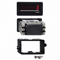
10. CONSTRUCTION: High impact plastic case with clear viewing window.
11. WEIGHT: 2 oz. (57 grams) [with battery]
Reed switches, mercury wetted contacts, snap action limit switches, and
used for powering RLC sensors with CUB
Counters, has the proper interface output for direct
drive to the H.S. CNT.
1. Burst to DC backlight power had a power line filter installed RLC
2. Self-recoverable loss of performance during EMI disturbance at 10 V/rms
Refer to the EMC Installation Guidelines section of this bulletin for
The front panel meets NEMA 4X/IP65 requirements for indoor use when
properly installed. Installation Category I, Pollution Degree 2. Panel gasket
and mounting clip included.
#LFIL0000 or equivalent at the unit.
to backlight power lines.
For operation without loss of performance:
additional information.
LCD segments may flicker during EMI disturbance.
Install power line filter RLC #LFIL0000 or equivalent at the unit.
PNP O.C. TRANSISTOR
OR BI-POLAR OUTPUT
FIG 2
+12 V
+18 V
+24 V
+5 V
R values for
+V
Fig 2 & 3
TRANSISTOR
NPN O.C.
FIG 3
2.2 K
10 K
16 K
24 K
R