CUB7W020 Red Lion Controls, CUB7W020 Datasheet - Page 3
CUB7W020
Manufacturer Part Number
CUB7W020
Description
COUNTER 8-DIGIT RED BKLT VOLT-IN
Manufacturer
Red Lion Controls
Series
CUB7r
Datasheet
1.CUB7W000.pdf
(4 pages)
Specifications of CUB7W020
Count Rate
30Hz
Number Of Digits/alpha
8
Input Type
Voltage
Voltage - Supply
9 V ~ 28 V
Display Type
LCD Backlit
Lead Free Status / RoHS Status
Lead free / RoHS Compliant
Output Type
-
Other names
RLCW72


L. S. INPUT, 30 CPS MAX.
The CUB7W accepts most machine control voltage signals. The input accepts
AC (50/60 Hz) or DC control voltages from 10 to 300 V at count speeds up to
30 cps. The unit counts on the positive going edge of the input signal.
BATTERY INSTALLATION
1. Remove all power to the unit before removing battery cover.
2. To remove battery cover, push upward in the direction of the arrow on rear
3. Remove old battery* and replace with an RLC battery (BNL10000).
4. Replace cover. The battery cover is keyed so that it cannot be placed upside
* - Dispose of properly.
INSTALLATION ENVIRONMENT
operating temperature and provides good air circulation. Placing the unit near
devices that generate excessive heat should be avoided.
Do NOT use solvents.
the bezel.
the keypad of the unit.
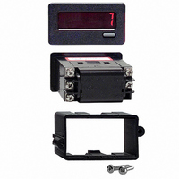
Installation
indoor use, when properly installed. The units are intended to be mounted into
an enclosed panel. The viewing window and reset button are factory sealed for
a washdown environment. A sponge rubber gasket and mounting clip are
provided for installing the unit in the panel cut-out.
1. Cut panel opening to specified dimensions. Remove burrs and clean around
2. Carefully remove and discard the center section of the gasket. Slide the
3. Install CUB7 unit through the panel cut-out until front bezel flange contacts
4. Slide the mounting clip over the rear of the unit until the clip is against the
cover (See drawing at right), until the cover unlatches. Pull cover straight
out from unit to fully remove.
Observe proper polarity when replacing battery as shown in drawing.
down. The arrow on the rear of the cover should point toward the top of the
CUB7 series when properly installed
The unit should be installed in a location that does not exceed the maximum
The bezel should be cleaned only with a soft cloth and neutral soap product.
Continuous exposure to direct sunlight may accelerate the aging process of
Do not use tools of any kind (screwdrivers, pens, pencils, etc.) to operate
The CUB7 series of products meets NEMA 4X/IP65 requirements for
The following procedure assures proper installation:
panel opening.
panel gasket over the rear of the unit to the back of the bezel. Insert the
mounting screws onto both sides of mounting clip. Tip of screw should
NOT project from hole in mounting clip.
the panel.
back of the panel. The mounting clip has latching features which engage
into mating features on the CUB7 housing.
WARNING: Any lead may be at hazardous live input potential.
WARNING: Lithium battery may explode if incinerated.
External wiring and devices connected to the unit must be rated
the same as applied signal input voltage and be properly isolated
from Class 2 or SELV circuitry.
3
5. Alternately tighten each screw to ensure uniform gasket pressure.
6. If gasket is not adequately compressed and the mounting screws can no
7. Repeat from step #5 for tightening mounting screws.
Note: It is necessary to hold the unit in place when sliding mounting clip
Visually inspect the front panel gasket. The gasket should be compressed to
about 75 to 80% of its original thickness. If not, gradually turn mounting
screws to further compress gasket.
longer be turned, loosen mounting screws, and check that mounting clip is
latched as close as possible to the panel.
into position.