ACM20-4-AC1-R-C Murata Power Solutions Inc, ACM20-4-AC1-R-C Datasheet - Page 5
ACM20-4-AC1-R-C
Manufacturer Part Number
ACM20-4-AC1-R-C
Description
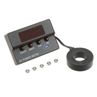
AC PWR METER 100A PWR FACTR READ
Manufacturer
Murata Power Solutions Inc
Series
ACM20r
Type
Multimeterr
Datasheet
1.ACM20-5-AC1-R-C.pdf
(6 pages)
Specifications of ACM20-4-AC1-R-C
Display Type
LED
Display Style
Red Characters, Black Background
Display Face Size
2.10" L x 1.43" W (53.3 x 36.3mm)
Display Digits
4
Display Digits - Height
0.360" (9.14mm)
Backlight
Without
Mounting Type
Panel Mount
Termination
Terminal Block
Voltage - Supply
85 ~ 264VAC
Dimensions
53.3 mm L x 36.3 mm W x 12.95 mm H
Mounting Style
Panel
Primary Voltage Rating
85 V to 264 V
Secondary Current Rating
100 A
Lead Free Status / RoHS Status
Lead free / RoHS Compliant
Measuring Range
-
Lead Free Status / Rohs Status
Lead free / RoHS Compliant
Other names
811-2203


PANEL INSTALLATION
PANEL CUTOUT
All connections to ACM20 power meters must be made after the unit
is securely attached to the panel and with all associated load and
supply voltages de energized (off), using extreme caution and observ-
ing all safety measures applicable to the user’s installation.
Care should be exercised when passing conductors through the
power meter’s built-in current transformer L1. The installed wire-
positions should be such that minimal mechanical forces are applied
to current transformer L1, TB1, or to the ACM20 power meter itself.
In high-vibration environments, it is strongly recommended that
adequate strain reliefs be used for all wiring.
(27.18)
0.093 (2.362) DIAMETER (4 REQUIRED)
1.07
ACM20
RECOMMENDED DRILL AND PANEL CUTOUT DIMENSIONS
INTERNAL CORNER RADII:
SIDE VIEW
PANEL
(33.93* - 36.22)
0.032 (0.81) MAX.
1.336* - 1.426
1.626 (41.30)
www.murata-ps.com/dpm
2-56 Hex Nuts (4 places)
Tighten each nut to 15 to 20 ozf-in (0.106 to 0.140 N-m).
Figure 5. Panel Installation
L1
(21.29* - 22.10)
0.838* - 0.870
Using Figure 5 as a guide, carefully insert the ACM20 assembly into
the panel opening. From the rear of the panel, install and then tighten
the four #2-56 hex nuts over the threaded studs. Tighten each nut to
15 to 20 ozf-in (0.106 to 0.140 N-m). Use only the factory-supplied
hardware as the use of substitute hardware could result in an unsafe
installation and/or adversely affect the reliability of the installation.
The recommended range of panel thickness that can be used with the
supplied hardware is 0.040 inches (1.0mm) to 0.25 inches (6.4mm).
Panel thicknesses outside of this range may require additional user-
supplied hardware or modifi cations. Front panel space permitting,
ACM20 power meters will fi t most existing ACA-20RM / ACA-20PC
ammeter cutouts, allowing for easy upgrading of existing installations.
* The two dimensions marked with an * specify the
minimum recommended panel cutout opening for
ACM20 power meters. Space permitting, the larger
dimensions noted (0.87in., and 1.426in.) should be
used. The panel opening must be centered vertically
and horizontally between the four 0.093 (2.362mm)
diameter holes.
03 Mar 2011 MPM_ACM20 Series.A09 Page 5 of 6
Four-Function AC Power Meters
ACM20 Series
email: sales@murata-ps.com