ACA-20RM-5-AC3-RL-ALM-C Murata Power Solutions Inc, ACA-20RM-5-AC3-RL-ALM-C Datasheet
ACA-20RM-5-AC3-RL-ALM-C
Specifications of ACA-20RM-5-AC3-RL-ALM-C


ACA-20RM-5-AC3-RL-ALM-C Summary of contents
Page 1
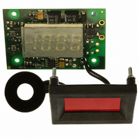
... LED-displays and a built-in bezel/fi lter assembly that includes metal fasteners. They are also panel cutout compatible with MPS’s DMS-20RM Series of rms- reading ac voltage monitors, making ACA-20RM-ALM ammeters the ideal upgrade for today’s sophisticated instrumentation. ...
Page 2
... Specifi ed accuracy applies to inputs with crest factors (CF 2.0, where CF ➃ All specifi ed maximum power supply currents are steady state; larger surge Sine-Wave Input ±0.4 Counts/ºC ACA-20RM-4-AC3-RL-ALM-C 001 Counts ACA-20RM-4-AC4-RL-ALM-C ACA-20RM-5-AC3-RL-ALM-C — Vdc ACA-20RM-5-AC4-RL-ALM-C TECHNICAL NOTES 140 Vac/47-63Hz 264 Vac/47-63Hz ...
Page 3
... To adjust the overcurrent alarm set-point level: A. Turn off power to the ACA-20RM-ALM (i.e., the power source con- nected to TB1). B. Carefully remove the shorting jumper across JP1 from its ‘normal operation position’ across terminals 2 and 3 and place it across JP1 terminals 1 and 2. C. Re-apply power to TB1 and, using a plastic insulated adjusting tool, adjust R3 so the ammeter’ ...
Page 4
... PANEL INSTALLATION All connections to ACA-20RM-ALM Series ammeters must be made after the ammeter is securely attached to the panel and with all associated load and supply voltages de-energized (off), using extreme caution and observing all safety measures applicable to the user’s installation. Care should be exercised when passing conductors through the amme- ter’ ...
Page 5
... M9 M9 BACK VIEW A B TB1 Lead Length 5.0 (127.0) min. 1.575 0.40 (40.00) (10.2) Diameter 0.984 (24.99) SIDE VIEW 0.551 (14.00) 0.480 (12.19) © 2011 Murata Power Solutions, Inc. email: sales@murata-ps.com 15 Mar 2011 MPM_ACA-20RM-ALM.A04 Page 1.400 (35.56) 1.024 (26.01) ...