PAXLVD00 Red Lion Controls, PAXLVD00 Datasheet - Page 7
PAXLVD00
Manufacturer Part Number
PAXLVD00
Description
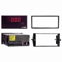
VOLTMETER DC 3 1/2-DIGIT
Manufacturer
Red Lion Controls
Series
PAX®LITEr
Type
Voltmeterr
Datasheet
1.PAXLVD00.pdf
(8 pages)
Specifications of PAXLVD00
Measuring Range
0 ~ 300V
Display Style
Red Characters, Black Background
Display Type
LED
Display Face Size
3.80" L x 1.95" W (96.5 x 49.5mm)
Display Digits
3.5
Display Digits - Height
0.560" (14.22mm)
Backlight
Without
Mounting Type
Panel Mount
Termination
Terminal Block
Voltage - Supply
115VAC,230 VAC
No. Of Digits / Alpha
3-1/2
Meter Function
DC Voltmeter
Meter Range
1.999V To 300V
Digit Height
14.2mm
Power Consumption
6VA
Operating Temperature Range
0°C To +60°C
Supply Voltage Ac, Min
115V
Accuracy
±0.1% %
Connection Type
Cage-Clamp
Cut Out, Panel
3.62×1.77 "
Dimensions
4.2"L×3.8"W×1.95"H
Display Digit Height
0.56 "
Display Resolution
1 mV to 1 V
Function
Voltage
Meter Type
Panel
Number Of Digits
3-1/2
Primary Type
Electronic
Range, Measurement
1.999 to 300 VDC
Special Features
Multi-Range Unit
Standards
CE Marked, cUL Recognized
Temperature, Operating
0 to 60 °C
Voltage, Input
1.999 to 300 V
Voltage, Supply
115/230 VAC
Character Size
0.56"
Display Font Color
Red
Rohs Compliant
Yes
Lead Free Status / RoHS Status
Lead free / RoHS Compliant
Lead Free Status / RoHS Status
Lead free / RoHS Compliant, Lead free / RoHS Compliant
Other names
RLC107
Available stocks
Company
Part Number
Manufacturer
Quantity
Price
Company:

Part Number:
PAXLVD00
Manufacturer:
Red Lion Controls
Quantity:
135


DIRECT CURRENT METER READOUT
should remain in the “OFF” position. The Input Range Jumper is set to the
current range being applied. It is possible to select a range higher than being
applied to get lower resolution. The Decimal Point switches are set to resolution
of the selected Input Range Jumper.
SCALING CURRENT METER READOUT
reading in terms of PSI, RPM, or some other unit of measure. The signal voltage
being measured can be generated by a transducer that senses the variations and
delivers a linear output voltage. To provide the desired readout at the specified
current, the current meter must be scaled.
Potentiometer which is accessible from the back of the meter. (Enabling the
Scale Potentiometer does NOT affect the calibration of the meter.) Place the
Decimal Point Switches to the proper location. The Input Range Jumper is set
to the current range being applied. Apply the meter power and the current signal.
Adjust the Scale Potentiometer to the desired value. Scaling to obtain a
numerical readout higher than the normal value of the current can also be
accomplished, in most cases, by selecting a lower current range. However, the
maximum current for the range must not be exceeded. (See Specifications for
maximum input currents.)
only zero amps can display a value of zero.
signal to a desired display value is performed by enabling the scale pot DIP
switch. If the meter appears to be indicating incorrectly or inaccurately, refer to
Troubleshooting before attempting to calibrate the meter.
performed by qualified technicians using appropriate equipment.
PAXLI
5.0 T
6.0 C
PROBLEM
NO DISPLAY
INCORRECT DISPLAY
OVER-RANGE INDICATION
When the application requires direct current meter readout, the Scale Switch
In many industrial applications, a current meter is required to display a
Place the Scale Switch in the “ON” position. This enables the Scale
This scaling only effects the span. There is no offset scaling. This means that
The meter has been fully calibrated at the factory. Scaling to convert the input
When recalibration is required (generally every 2 years), it should only be
ROUBLESHOOTING
ALIBRATION
For further assistance, contact technical support at the appropriate company numbers listed.
REMEDIES
CHECK: Power switch and line voltage
CHECK: Input jumper position
CHECK: Scaling adjustment pot DIP switch position
ADJUST: Scaling pot
VERIFY: Input Signal
CHECK: Input jumper position
VERIFY: Input signal
7
COMMON
+SIGNAL
EXAMPLE: The Pax Current Meter has been connected to measure a circuit
Input Calibration
calibrated. Also verify that the precision signal source is connected and ready.
Allow a 30 minute warm-up period before calibrating the meter.
1. Place jumper in 2 V range (PAXLV) or 2 mA range (PAXLI).
2. Set the DIP switch off to disable the scaling pot.
3. Apply half scale input signal.
4. Adjust calibration potentiometer as necessary for the display to read 1000
5. Apply zero signal and ensure display reads zero.
6. Apply full scale signal and ensure display reads 1999.
Note: Any individual range may be recalibrated (scaled) to 0.1% accuracy with
current to 120.0 mA maximum. However, in this application, the display is to
indicate percent of load current with 120.0 mA equivalent to 100.0 percent.
The scale potentiometer is adjusted to reduce the normal 120.0 mA signal
input display reading of 120.0 to indicate the desired reading of 100.0 on the
display. Scaling to obtain a numerical readout higher than the normal value
of the current can also be accomplished in most cases by selecting a lower
current range. However, the maximum current for the range must not be
exceeded. (See Specifications for maximum input currents.)
Before starting, verify that the Input Range Jumper is set for the range to be
Then perform the following procedure:
(ignore decimal point).
appropriate calibration equipment.
with an accuracy of 0.01% or better and an external meter with an
accuracy of 0.005% or better.
WARNING: Calibration of this meter requires a signal source
0-199.9µA/
0-1.999mA
0-19.99mA
0-199.9mA
0-1.999A
199.9mV
BLOCK DIAGRAM PAXLI
.1
900
90
9
1
Ω
Ω
Ω
Ω
Ω
SCALE
POT
S5
+VDC
S3
S2
S1
S4