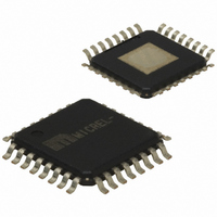
SY87729LHI Micrel Inc, SY87729LHI Datasheet - Page 8

SY87729LHI
Manufacturer Part Number
SY87729LHI
Description
IC SYNTHESIZER FRACT 3.3V 32TQFP
Manufacturer
Micrel Inc
Type
Fractional Synthesizerr
Datasheet
1.SY87729LHY.pdf
(14 pages)
Specifications of SY87729LHI
Input
PECL
Output
PECL
Frequency - Max
365MHz
Voltage - Supply
3.15 V ~ 3.45 V
Operating Temperature
-40°C ~ 85°C
Mounting Type
Surface Mount
Package / Case
32-TQFP Exposed Pad, 32-eTQFP, 32-HTQFP, 32-VQFP
Frequency-max
365MHz
For Use With
576-1404 - BOARD EVAL N SY87729 EXPERIMENT
Lead Free Status / RoHS Status
Contains lead / RoHS non-compliant
Available stocks
Company
Part Number
Manufacturer
Quantity
Price
Micrel, Inc.
Lock Detector
synthesizers by verifying that both PLL have achieved lock.
The LOCKED output asserts active high only when this is
the case, that is, both PLL are locked.
both simple and robust. Each phase-frequency detector
provides a charge pump output that is the logical OR of
pump up and pump down pulses.
with a pulse width discriminator. Once each reference clock
rising edge, the discriminator will produce a pulse, only if
the phase difference between the feedback divider and the
reference input is too large.
PLL that is out of lock, is declared to be in lock only if 256
consecutive reference clocks have NO large phase errors,
as reported by the pulsewidth discriminator. Any large phase
error event, even a single one, that arrives before lock is
declared, will reset the circuit.
phase-difference than small-phase-difference events occur
that is, if over time, a net of 256 large-phase-difference
events occur. That is accomplished by counting up when
large-phase-difference events occur and counting down in
the case of small-phase events.
Wrapper Synthesizer
processed by a more classical PLL circuit, as shown in
Figure 3.
the fractional-N loop. This comes in handy where digital
wrapper and/or FEC is implemented. The wrapper
synthesizer generates just a few ratios near 1.
of M and N, the dividers, as per:
Wrapper Phase-Frequency Detector
for the charge pump, and also generates delta phase for
the lock detector.
M9999-062807
hbwhelp@micrel.com or (408) 955-1690
The SY87729L ensures proper operation of both
The SY87729L implements a digital lock detector that is
The lock detect circuit processes this charge pump output
These pulses are subsequently processed digitally. A
Once in lock, a PLL is declared out of lock if more large-
The frequency generated by the fractional-N PLL is further
This circuit further modifies the frequency generated by
The wrapper modifies the frequency based on the values
This circuit generates pump up and pump down signals
540MHz
×
Frequency
f
REF
(f
FNOUT
Input
≤
)
729MHz
≤
Figure 3. Wrapper Architecture
f
WROUT
M
=
M
N
Frequency
Detector/
Charge
×
Phase-
Pump
f
FNOUT
Loop Filter
N
=
M
N
×
VCO
⎡
⎢
⎢
⎣
P –
Q
P–1
Q
Output
Frequency
(f
WROUT
P–1
+
Q
)
P
⎤
⎥
⎥
⎦
8
Wrapper Charge Pump
frequency detector into current pulses. Charge pump current
is fixed at about 20µA. An external loop filter integrates
these current pulses into a control voltage.
Wrapper VCO
and operation, so that the center frequency trim circuit can
center both the fractional-N VCO and the wrapper VCO at
about the same frequency.
Wrapper M Divider
the wrapper synthesizer modifies the fractional-N output
frequency. The division ratio is selected via MicroWire™,
as the 3-bit MdivSel register, as per Table 3 .
divisors 14, 15, 16, 17 and 18. The second set consists of
31 and 32. Both M and N must be chosen from the same
set. For example, an N divisor of 31 and an M divisor of 17
results in undefined behavior. The
smaller than
Wrapper N Divider
wrapper synthesizer modifies the fractional-N output
frequency. The division ratio is selected via MicroWire™,
as the 3-bit NdivSel register, as per Table 4.
This circuit converts the pump signals from the phase-
This circuit matches the fractional-N VCO in construction
This circuit forms the denominator of the ratio by which
The divisors are in two sets. The first set consists of the
This circuit forms the numerator of the ratio by which the
MdivSel2
NdivSel2
0
0
0
0
1
1
1
1
0
0
0
0
1
1
1
1
Table 3. MdivSel Divisor Control
Table 4. NdivSel Divisor Control
17
14
, that is,
MdivSel1
NdivSel1
0
0
1
1
0
0
1
1
0
0
1
1
0
0
1
1
18
14
is not allowed.
MdivSel0
NdivSel0
⎛
⎜
⎝
0
1
0
1
0
1
0
1
0
1
0
1
0
1
0
1
M
N
⎞
⎟
⎠
ratio must be kept
Divisor
Divisor
AnyClock
SY87729L
16
16
18
17
31
14
32
15
16
16
18
17
31
14
32
15
®


