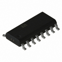
SY100EL15ZC Micrel Inc, SY100EL15ZC Datasheet - Page 4

SY100EL15ZC
Manufacturer Part Number
SY100EL15ZC
Description
IC DISTRIBUTION CLOCK 1:4 16SOIC
Manufacturer
Micrel Inc
Type
Fanout Buffer (Distribution), Multiplexerr
Series
100EL, Precision Edge®r
Datasheet
1.SY100EL15ZG.pdf
(5 pages)
Specifications of SY100EL15ZC
Number Of Circuits
1
Ratio - Input:output
2:4
Differential - Input:output
Yes/Yes
Input
ECL, PECL
Output
ECL, PECL
Voltage - Supply
3 V ~ 3.8 V
Operating Temperature
0°C ~ 85°C
Mounting Type
Surface Mount
Package / Case
16-SOIC (3.9mm Width)
Number Of Clock Inputs
2
Operating Supply Voltage (min)
-4.2V
Operating Supply Voltage (typ)
-5V
Operating Supply Voltage (max)
-5.7V
Package Type
SOIC W
Operating Temp Range
0C to 85C
Operating Temperature Classification
Commercial
Signal Type
ECL
Mounting
Surface Mount
Pin Count
16
Lead Free Status / RoHS Status
Contains lead / RoHS non-compliant
Frequency-max
-
Lead Free Status / RoHS Status
Not Compliant, Contains lead / RoHS non-compliant
Available stocks
Company
Part Number
Manufacturer
Quantity
Price
Part Number:
SY100EL15ZC
Manufacturer:
SYNERGY
Quantity:
20 000
Micrel, Inc.
V
NOTES:
1. This table replaces the three traditionally seen in ECL 100K data books. The same DC parameter values at V
2. V
3. V
4. V
V
NOTE:
1. Skews are specified for identical LOW-to-HIGH or HIGH-to-LOW
M9999-031006
hbwhelp@micrel.com or (408) 955-1690
Symbol
V
V
V
V
V
V
I
I
I
V
Symbol
t
t
t
t
V
V
t
t
EE
EE
IH
IL
EE
PD
skew
S
H
r
f
100EL DC ELECTRICAL CHARACTERISTICS
OH
OL
OHA
OLA
IH
IL
BB
AC ELECTRICAL CHARACTERISTICS
PP
CMR
range of –4.2V to –5.5V. Outputs are terminated through a 50 resistor to –2.0V except where otherwise specified on the individual data sheets.
transitions.
IN
IN
IN
= V
= V
= V
= V
= V
EE
EE
IH
IH
IL
(Max).
(Max) or V
(Min) or V
(Min.) to V
Output HIGH Voltage
Output LOW Voltage
Output HIGH Voltage
Output LOW Voltage
Input HIGH Voltage
Input LOW Voltage
Input High Current
Input LOW Current
Power Supply Current
Output Reference Voltage
(Min) to V
Propagation Delay
CLK to Q (Diff)
CLK to Q (SE)
SCLK to Q
Part-to-Part Skew
Within-Device Skew
Setup Time EN
Hold Time EN
Minimum Input
Swing
Common Mode
Range
Output Rise/Fall Times Q
(20% – 80%)
Parameter
Parameter
IL
IL
(Max).
(Min).
EE
EE
(Max); V
(Max.); V
(1)
(4)
(2)
(3)
CLK
CLK
(2)
(3)
CC
CC
= GND
= GND
–1165
–1810
–1085
–1830
–1095
–1.38
Min.
Min.
–2.0
0.5
460
410
410
150
400
250
—
—
—
—
—
—
T
T
A
A
= –40 C
= –40 C
(1)
–1555
–1555
–1475
–1.26
Max.
–880
–880
Max.
–0.4
150
660
710
710
200
35
50
—
—
—
—
—
—
–1025
–1810
–1035
–1165
–1810
–1.38
Min.
Min.
–2.0
470
420
325
420
150
400
250
0.5
—
—
—
—
—
T
T
A
A
4
= 0 C
= 0 C
–1620
–1610
–1475
–1.26
Max.
–880
–880
Max.
–0.4
150
670
720
720
200
575
—
—
35
50
—
—
—
–1025
–1810
–1035
–1165
–1810
–1.38
Min.
Min.
–2.0
470
420
420
150
400
250
325
0.5
—
—
—
—
—
T
T
A
A
–1705
= +25 C
= +25 C
–955
Typ.
Typ.
25
—
—
—
—
—
—
—
—
—
—
—
—
—
—
—
—
—
–1620
–1610
–1475
–1.26
EE
–880
Max.
–880
150
Max.
–0.4
35
670
720
720
200
575
—
—
50
—
—
—
= –4.5V now apply across the full V
–1025
–1810
–1035
–1165
–1810
–1.38
Min.
Min.
–2.0
500
450
470
150
400
250
325
0.5
—
—
—
—
—
T
T
A
A
= +85 C
= +85 C
Precision Edge
–1620
–1610
–1475
–1.26
Max.
–880
–880
Max.
–0.4
150
700
750
750
200
575
38
50
—
—
—
—
—
SY100EL15
SY10EL15
Unit
Unit
mV
mV
mV
mV
mV
mV
mA
mV
ps
ps
ps
ps
ps
V
V
A
A
EE
®


