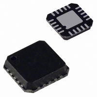
ADF4106BCP Analog Devices Inc, ADF4106BCP Datasheet - Page 2

ADF4106BCP
Manufacturer Part Number
ADF4106BCP
Description
IC PLL FREQ SYNTHESIZER 20-LFCSP
Manufacturer
Analog Devices Inc
Type
Clock/Frequency Synthesizer (RF)r
Datasheet
1.ADF4106BCPZ.pdf
(24 pages)
Specifications of ADF4106BCP
Rohs Status
RoHS non-compliant
Pll
Yes
Input
CMOS
Output
Clock
Number Of Circuits
1
Ratio - Input:output
2:1
Differential - Input:output
Yes/No
Frequency - Max
6GHz
Divider/multiplier
No/No
Voltage - Supply
2.7 V ~ 3.3 V
Operating Temperature
-40°C ~ 85°C
Mounting Type
Surface Mount
Package / Case
20-LFCSP
Frequency-max
6GHz
Number Of Elements
1
Supply Current
10.5(Typ)mA
Pll Input Freq (min)
20MHz
Pll Input Freq (max)
6GHz
Operating Supply Voltage (typ)
3V
Operating Temp Range
-40C to 85C
Package Type
LFCSP EP
Output Frequency Range
Up to 325MHz
Operating Supply Voltage (min)
2.7V
Operating Supply Voltage (max)
3.3V
Operating Temperature Classification
Industrial
Pin Count
20
For Use With
EVAL-ADF4106EBZ1 - BOARD EVAL FOR ADF4106
Lead Free Status / RoHS Status
Not Compliant
Available stocks
Company
Part Number
Manufacturer
Quantity
Price
Company:
Part Number:
ADF4106BCP-REEL7
Manufacturer:
AD
Quantity:
10 342
Part Number:
ADF4106BCP-REEL7
Manufacturer:
ADI/亚德诺
Quantity:
20 000
Company:
Part Number:
ADF4106BCPZ
Manufacturer:
HITTITE
Quantity:
1 492
Part Number:
ADF4106BCPZ
Manufacturer:
ADI/亚德诺
Quantity:
20 000
Company:
Part Number:
ADF4106BCPZ#
Manufacturer:
ADI
Quantity:
1 207
Part Number:
ADF4106BCPZ-R7
Manufacturer:
ADI/亚德诺
Quantity:
20 000
Company:
Part Number:
ADF4106BCPZ-RL7
Manufacturer:
AD
Quantity:
333
ADF4106
TABLE OF CONTENTS
Specifications ..................................................................................... 3
Absolute Maximum Ratings ............................................................ 5
Pin Configurations and Function Descriptions ........................... 6
Typical Performance Characteristics ............................................. 7
General Description ......................................................................... 9
REVISION HISTORY
2/10—Rev B to Rev. C
Changes to Figure 4 and Table 4 ..................................................... 6
Changes to Figure 12 ........................................................................ 8
Updated Outline Dimensions ....................................................... 20
Changes to Ordering Guide .......................................................... 21
6/05—Rev A to Rev. B
Updated Format .................................................................. Universal
Changes to Figure 1 .......................................................................... 1
Changes to Table 1 ............................................................................ 3
Changes to Table 2 ............................................................................ 4
Changes to Table 3 ............................................................................ 5
Changes to Figure 3 and Figure 4 ................................................... 6
Timing Characterisitics ............................................................... 4
ESD Caution .................................................................................. 5
Reference Input Section ............................................................... 9
RF Input Stage ............................................................................... 9
Prescaler (P/P +1) ......................................................................... 9
A Counter and B Counter ........................................................... 9
R Counter ...................................................................................... 9
Rev. C | Page 2 of 24
Applications ..................................................................................... 18
Outline Dimensions ....................................................................... 20
Changes to Figure 6 ........................................................................... 7
Changes to Figure 10 ......................................................................... 7
Deleted TPC 13 and TPC 14 ............................................................ 8
Changes to Figure 15 ......................................................................... 8
Changes to Figure 20 Caption ...................................................... 10
Updated Outline Dimensions ....................................................... 20
Changes to Ordering Guide .......................................................... 21
5/03—Rev 0 to Rev. A
Edits to Specifications ....................................................................... 2
Edits to TPC 11 .................................................................................. 7
Updated Outline Dimensions ....................................................... 19
10/01—Revision 0: Initial Revision
Phase Frequency Detector (PFD) and Charge Pump ............ 10
MUXOUT and Lock Detect ...................................................... 10
Input Shift Register .................................................................... 10
The Function Latch .................................................................... 16
The Initialization Latch ............................................................. 17
Local Oscillator for LMDS Base Station Transmitter ............ 18
Interfacing ................................................................................... 19
PCB Design Guidelines for Chip Scale Package .................... 19
Ordering Guide .......................................................................... 21


