1410232-1 TE Connectivity, 1410232-1 Datasheet - Page 3
1410232-1
Manufacturer Part Number
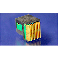
1410232-1
Description
MULTIGIG RT T1 1" DC SE H-LFT
Manufacturer
TE Connectivity
Series
Noner
Specifications of 1410232-1
Product Type
Connector
Type Of Connector
Daughtercard
Mount Angle
Right Angle
Termination Type
Single-Ended (SE)
Module Type
Left
Data Rate (gb/s)
3.125
Solder Tail Contact Plating
Tin-Lead over Nickel
Card Slot Pitch (mm [in])
25.4 [1]
Number Of Columns
8
Post Material
Brass
Post Plating
Nickel
Contact Base Material
Phosphor Bronze
Contact Plating, Mating Area, Material
Gold
Housing Material
Liquid Crystal Polymer (LCP)
Housing Color
Black
Ul Flammability Rating
UL 94V-0
Density
141 lines/inch
Rohs/elv Compliance
RoHS compliant, ELV compliant
Lead Free Solder Processes
Not relevant for lead free process
Rohs/elv Compliance History
Always was RoHS compliant


W ithstanding voltage.
Tem perature rise vs current.
Vibration, sinusoidal.
Mechanical shock.
Durability.
Mating force.
Unm ating force.
Com pliant pin insertion.
Com pliant pin retention.
Rev D
Test Description
1 m inute hold with no breakdown or
flashover.
30 C m axim um tem perature rise at
1 am pere load, single circuit in free
air using therm ography.
No discontinuities of 1 m icrosecond
or longer duration.
See Note.
No discontinuities of 1 m icrosecond
or longer duration.
See Note.
See Note.
0.75 N [2.7 ozf] m axim um per
contact. Average for entire
connector.
0.15 N [.54 ozf] m inim um per
contact. Average for entire
connector.
31 N [7 lbf] m axim um per pin
average.
13.35 N [3 lbf] m inim um .
Figure 1 (continued)
MECHANICAL
Requirem ent
EIA-364-20, Condition I.
500 volts AC peak or DC at sea
level.
Test between any adjacent pair of
signal contacts, or from any signal
contact to an adjacent ground pin of
m ated specim ens.
EIA-364-70, Method 1.
Stabilize at a single current level
until 3 readings at 5 m inute intervals
are within 1 C.
EIA-364-28, Test Condition II.
Subject m ated specim ens to 10-
500-10 Hz traversed in 15 m inutes
with 1.5 m m [.06 in] m axim um total
excursion. Two hours in each of 3
m utually perpendicular planes.
EIA-364-27, Method H.
Subject m ated specim ens to 30 G's
half-sine shock pulses of 11
m illiseconds duration. Three shocks
in each direction applied along 3
m utually perpendicular planes, 18
total shocks.
EIA-364-9.
Mate and unm ate specim ens for
200 cycles at a m axim um rate of
500 cycles per hour.
EIA-364-13.
Measure force necessary to m ate
specim ens at a m axim um rate of
12.7 m m [.5 in] per m inute.
EIA-364-13.
Measure force necessary to unm ate
specim ens at a m axim um rate of
12.7 m m [.5 in] per m inute.
AMP Spec 109-41.
Measure force necessary to
correctly apply a connector
assem bly to a printed circuit board
at a m axim um rate of 12.7 m m [.5
in] per m inute.
AMP Spec 109-30.
Measure force necessary to unseat
a single pin in a correctly applied
connector assem bly from its printed
circuit board hole at a m axim um
rate of 12.7 m m [.5 in] per m inute.
Procedure
108-2072
3 of 10
Related parts for 1410232-1
Image
Part Number
Description
Manufacturer
Datasheet
Request
R


Part Number:
Description:
Manufacturer:
TE Connectivity
Datasheet:


Part Number:
Description:
Manufacturer:
TE Connectivity
Datasheet:

Part Number:
Description:
Manufacturer:
TE Connectivity
Datasheet:

Part Number:
Description:
Manufacturer:
TE Connectivity
Datasheet:


Part Number:
Description:
Manufacturer:
TE Connectivity
Datasheet:

Part Number:
Description:
Manufacturer:
TE Connectivity
Datasheet: